
Method and Apparatus for Determining Audio Spatial Quality

a spatial quality and audio technology, applied in the field of audio spatial quality assessment, can solve the problems of lossy data compression, file compression using lossy methods suffering from a variety of distortions, and may or may not be perceivable to the human ear or eye, and limit human perception

Active Publication Date: 2008-10-09
APPLE INC
View PDF25 Cites 25 Cited by
  • Summary
  • Abstract
  • Description
  • Claims
  • Application Information

AI Technical Summary

Benefits of technology

[0017]Broadly speaking, the invention pertains to techniques for assessing the quality of processed audio. More specifically, the invention pertains to techniques for assessing spatial and non-spatial distortions of a processed audio signal. Th...

Problems solved by technology

Conversely, lossy data compression is commonly used to compress multimedia data, including audio, video, and picture files.
However, files that have been compressed using lossy methods suffer from a variety of distortions, which may or may not be perceivable to the human ear or eye.
Lossy methods often compress by focusing on the limitations of human perception, removing data that cannot be perceived by the average person.
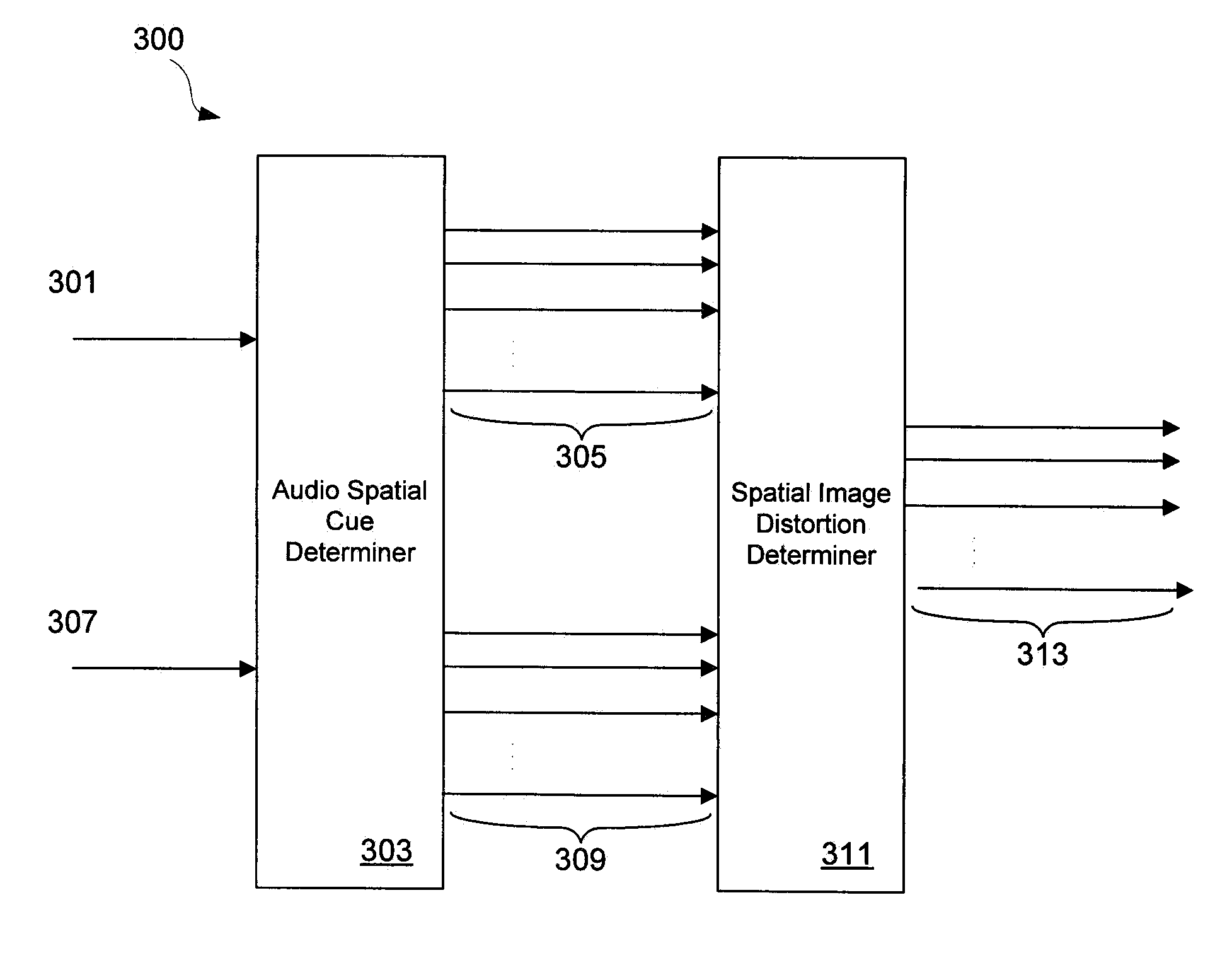
However, objective assessment techniques do not employ appropriate measures to estimate deviations of the evoked auditory spatial image of a multi-channel audio signal (e.g., 2-channel stereo, 5.1 channel surround sound, etc.).
The potential coding distortions caused by joint-channel coding techniques cannot be appropriately estimated by conventional assessment tools such as PEAQ simply because each audio channel is processed separately and properties of the spatial image are not taken into account.
For many types of audio signals this lack of spatial image distortion analysis can cause inaccurate objective quality estimations, leading to unsatisfactory quality assessments.
Thus, an audio signal may have a high quality rating according to the PEAQ standard, yet have severe spatial image distortions.
This is highly undesirable in the case of high fidelity or high definition sound recordings where spatial cues are crucial to the recording, such as multi-channel (i.e., two or more channels) sound systems.

Method used


Image

  • Method and Apparatus for Determining Audio Spatial Quality
  • Method and Apparatus for Determining Audio Spatial Quality
  • Method and Apparatus for Determining Audio Spatial Quality

Examples


implementation example

[0068]An exemplary implementation of a spatial audio quality assessment is described below.

[0069]The estimation of spatial cues can be implemented in various ways. Two examples are given in Frank Baumgarte and Christof Faller, “Binaural Cue Coding—Part I: Psychoacoustic Fundamentals and Design Principles,” IEEE Trans. Audio, Speech, and Language Proc., Vol. 11, No. 6, November 2003, which is hereby incorporated by reference in its entirety, and in “Binaural Cue Coding—Part II: Schemes and Applications,” referenced above. Alternative implementations can be found in ISO / IEC, “Information Technology—MPEG audio technologies—Part 1: MPEG Surround,” ISO / IEC FDIS 23003-1:2006(E), Geneva, 2006, and ISO / IEC, “Technical Description of Parametric Audio Coding for High Quality Audio,” ISO / IEC 14496-3-2005(E) Subpart 8, Geneva, 2005, both of which are hereby incorporated by reference in their entirety.

[0070]A spatial cue analyzer 800 is shown in FIG. 8. The input consists of the audio signals of...


PUM


Abstract

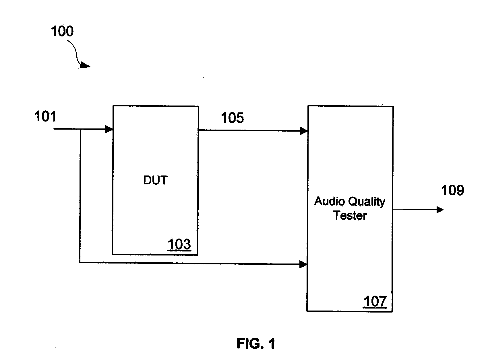
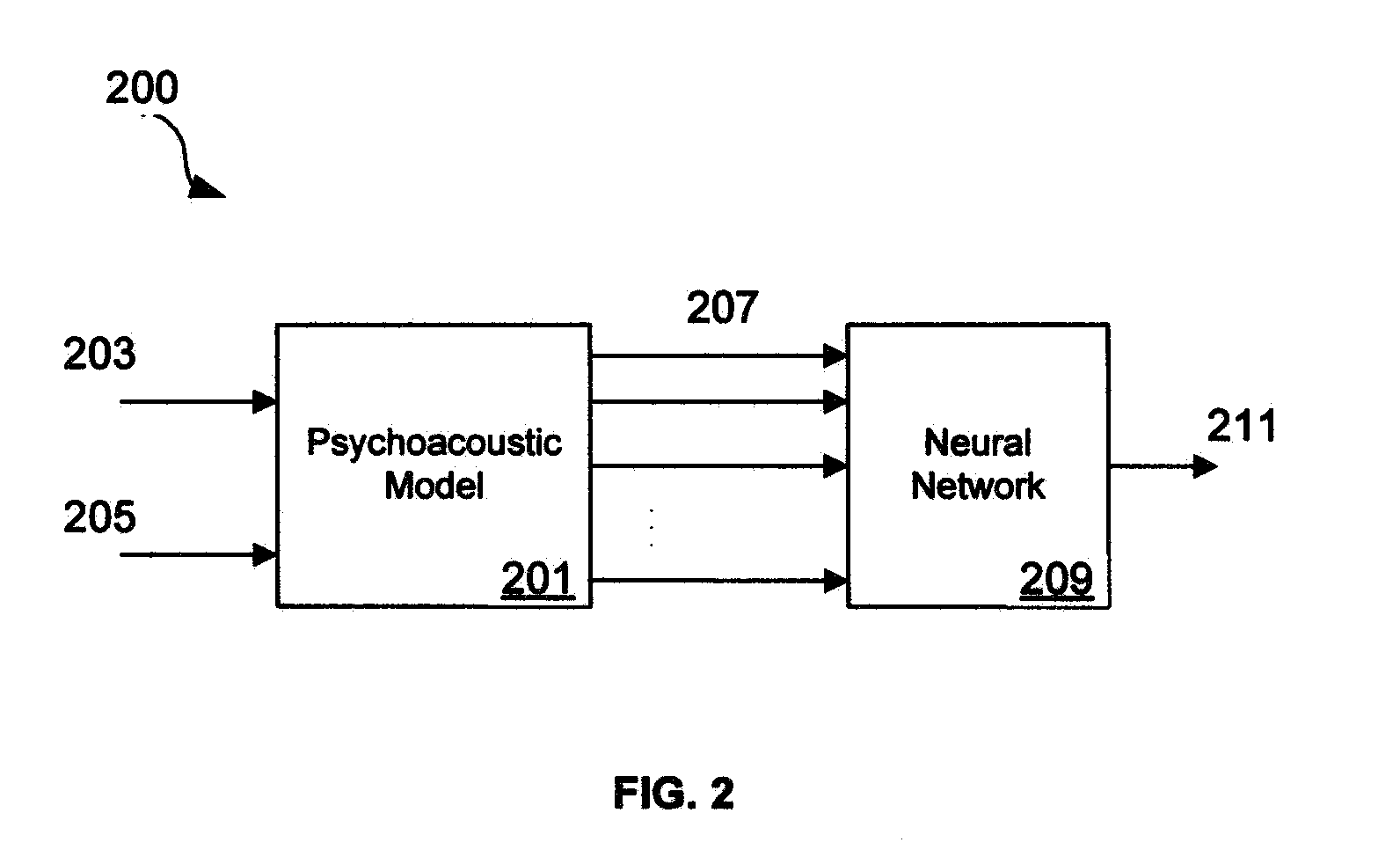
Techniques for evaluating the audio quality of an audio test signal are disclosed. These techniques provide a quality analysis that takes into account spatial audio distortions between the audio test signal and a reference audio signal. These techniques involve, for example, determining a plurality of audio spatial cues for an audio test signal, determining a corresponding plurality of audio spatial cues for an audio reference signal, comparing the determined audio spatial cues of the audio test signal to the audio spatial cues of the audio reference signal, and determining the audio quality of the audio test signal.

Description

BACKGROUND OF THE INVENTION[0001]1. Field of the Invention[0002]In general, the invention relates to sound quality assessment of processed audio files, and, more particularly, to evaluation of the sound quality of multi-channel audio files.[0003]2. Description of the Related Art[0004]In recent years, there has been a proliferation of digital media players (e.g., media players capable of playing digital audio files). Typically, these digital media players play digitally encoded audio or video files that have been “compressed” using any number of digital compression methods. Digital audio compression can be classified as ‘lossless’ or ‘lossy’. Lossless data compression allows the recovery of the exact original data that was compressed, while data compressed with lossy data compression yields data files that are different from the source files, but are close enough to be useful in some way. Typically, lossless compression is used to compress data files, such as computer programs, text ...

Claims


Application Information

Patent Timeline
IPC IPC(8): G10L19/00
CPCG10L19/008G10L25/30G10L25/69H04S3/00H04S2420/03
Inventor BAUMGARTE, FRANK M.
Owner APPLE INC
Learn More