
Back-up table for chip mounter

a chip mounter and back-up table technology, applied in the direction of lead-acid accumulators, electrochemical generators, manufacturing tools, etc., can solve the problems of reducing manufacturing costs, affecting the stability of the chip mounter, and the inability to maintain the horizontality of the upper table, so as to reduce manufacturing costs and simplify the entire structure

Active Publication Date: 2008-10-16
HANWHA AEROSPACE CO LTD
View PDF5 Cites 6 Cited by
  • Summary
  • Abstract
  • Description
  • Claims
  • Application Information

AI Technical Summary

Benefits of technology

[0012]The present invention provides a back-up table for a chip mounter capable of simplifying the entire structure, reducing manufacturing costs, and freely adjusting the height of the back-up table in a multistage manner.

Problems solved by technology

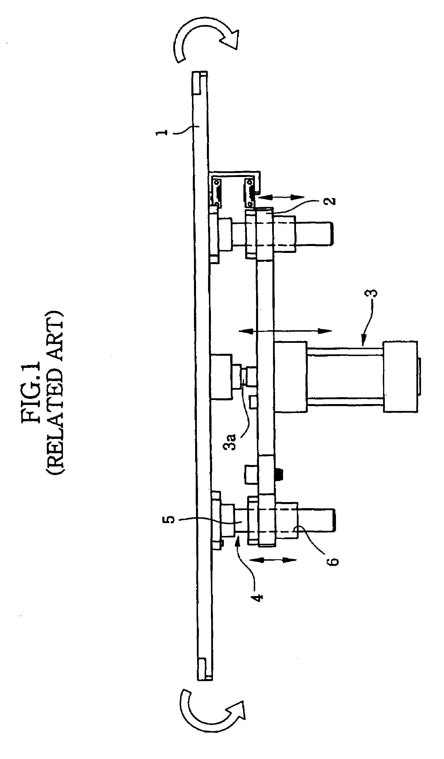
However, in the conventional back-up table for a chip mounter as described above, horizontality of the upper table generally cannot be maintained upon upward movement of the upper table, and therefore the printed circuit board cannot be uniformly supported.
However, the conventional back-up table for a chip mounter has disadvantages of complicating the entire structure and increasing the entire manufacturing cost.

Method used


Image

  • Back-up table for chip mounter
  • Back-up table for chip mounter
  • Back-up table for chip mounter

Examples


Embodiment Construction

[0031]Embodiments of the present invention will be described below in more detail with reference to the accompanying drawings. The present invention may, however, be embodied in different forms and should not be construed as being limited to the embodiments set forth herein. Rather, these embodiments are provided to assist one skilled in the art to understand the invention. Also, like reference numerals refer to like elements throughout the accompanying figures.

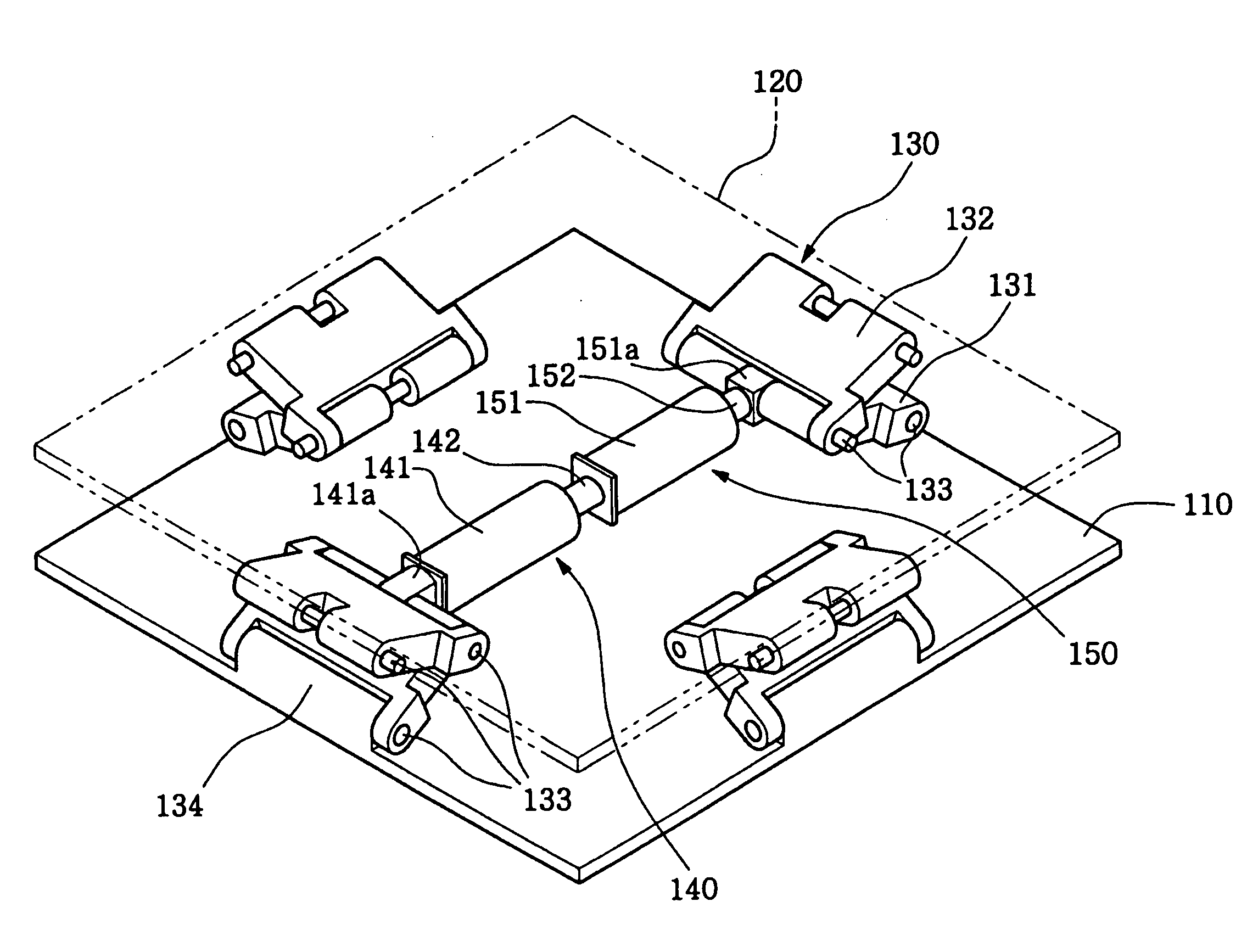
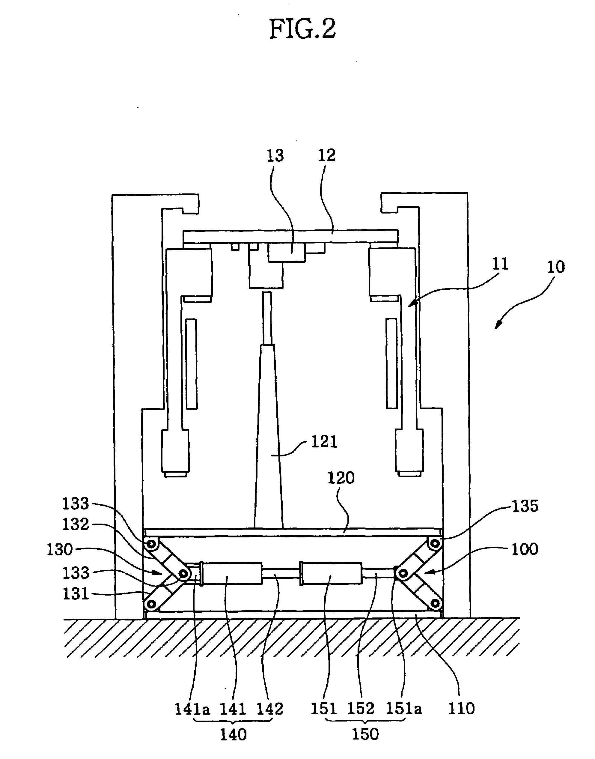
[0032]FIG. 2 is a front view showing installation of a back-up table 100 for a chip mounter 10 in accordance with an exemplary embodiment of the present invention. FIG. 3 is a perspective view showing a folded state of the back-up table for a chip mounter shown in FIG. 2. FIG. 4 is a perspective view showing an unfolded state of the back-up table for a chip mounter shown in FIG. 2, and FIG. 5 is a perspective view of a link unit of the back-up table for a chip mounter shown in FIG. 2.

[0033]As shown in FIGS. 2 to 5, a back-up ...


PUM


Abstract

A back-up table for a chip mounter. The back-up table for a chip mounter includes a base plate, a back-up plate spaced a predetermined distance from the base plate to support a back-up pin that supports a printed circuit board, and at least one set of link units installed between the base plate and the back-up plate and facing opposite to each other. The back-up table further comprises a first driving part installed between the opposite facing link units and operating the link units to raise and lower the back-up plate, and a second driving part serially connected to the first driving part.

Description

CROSS-REFERENCE TO RELATED APPLICATION[0001]This application claims the benefit of Korean Patent Application No. 2007-0036392, filed Apr. 13, 2007, the entire content of which is hereby incorporated herein by reference.BACKGROUND OF THE INVENTION[0002]1. Field of the Invention[0003]The present invention relates to a back-up table for a chip mounter, and more particularly, to a back-up table for a chip mounter used in equipment for supporting a printed circuit board on a certain position in the chip mounter.[0004]2. Description of the Related Art[0005]In general, a chip mounter is a device for mounting small electronic components such as a semiconductor chip on a printed circuit board. The chip mounter picks up electronic components supplied through a component supply device using a pickup mechanism movable on an X- and Y-axis frame, and then mounts the components onto the printed circuit board conveyed by a board conveyance device.[0006]When the electronic components are completely ...

Claims


Application Information

Patent Timeline
IPC IPC(8): B23P19/00
CPCH05K13/0069Y10T29/53974Y10T29/53174Y10T29/5313Y10T29/53183Y10T29/53187Y10T29/53961Y10T29/53135Y10T29/53178H01L21/67H01L21/02
Inventor LEE, TAE-YOUNG
Owner HANWHA AEROSPACE CO LTD
Learn More