High Impact Shearing Element

a cutting element and high impact resistance technology, applied in the field of high impact resistant tools, can solve the problems of reducing or eliminating the efficacy of cutting elements, reducing or eliminating the effect of cutting elements, and often being subjected to intense forces on inserts, etc., to achieve the effect of high impact resistan

Inactive Publication Date: 2008-10-16
SCHLUMBERGER TECH CORP
View PDF99 Cites 23 Cited by
  • Summary
  • Abstract
  • Description
  • Claims
  • Application Information

AI Technical Summary

Benefits of technology

[0012]The carbide substrate may comprise a metal concentration of 2 to 10 percent metal by volume. The carbide substrate may comprise a volume from 0.010 to 0.500 cubic inches. The faces may be generally concave. The faces may be generally convex. The faces may comprise equal areas. The sintered body may comprise a rim at the working surface. The rim may be chamfered. The rim may be rounded. The sintered body may comprise a metal concentration of less than 4 percent by volume. The sintered body may be monolithic. The tool may be adapted to be used in asphalt picks, drill bits, shear bits, percussion bits, trenchers, coal picks, o

Problems solved by technology

Such inserts are often subjected to intense forces, torques, vibration, high temperatures and temperature differentials during operation.
As a result, stresses within the structure may begin to form.
Drill bits for example may exhibit stresses aggravated by drilling anomalies during well boring operations such as bit whirl or bounce often resulting in spalling, delamination or fracture of the super hard abrasive lay

Method used


Image

  • High Impact Shearing Element
  • High Impact Shearing Element
  • High Impact Shearing Element

Examples


Embodiment Construction

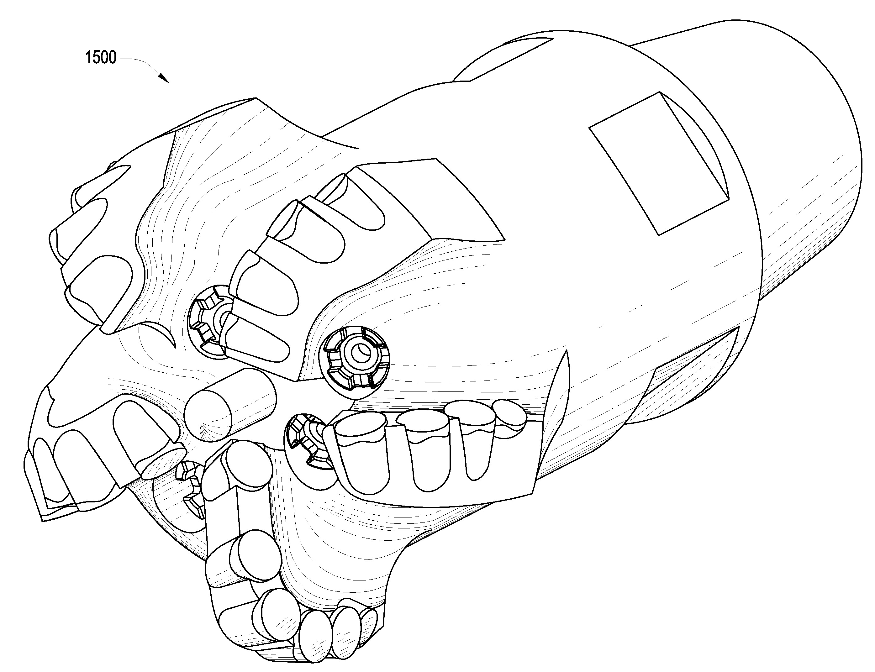
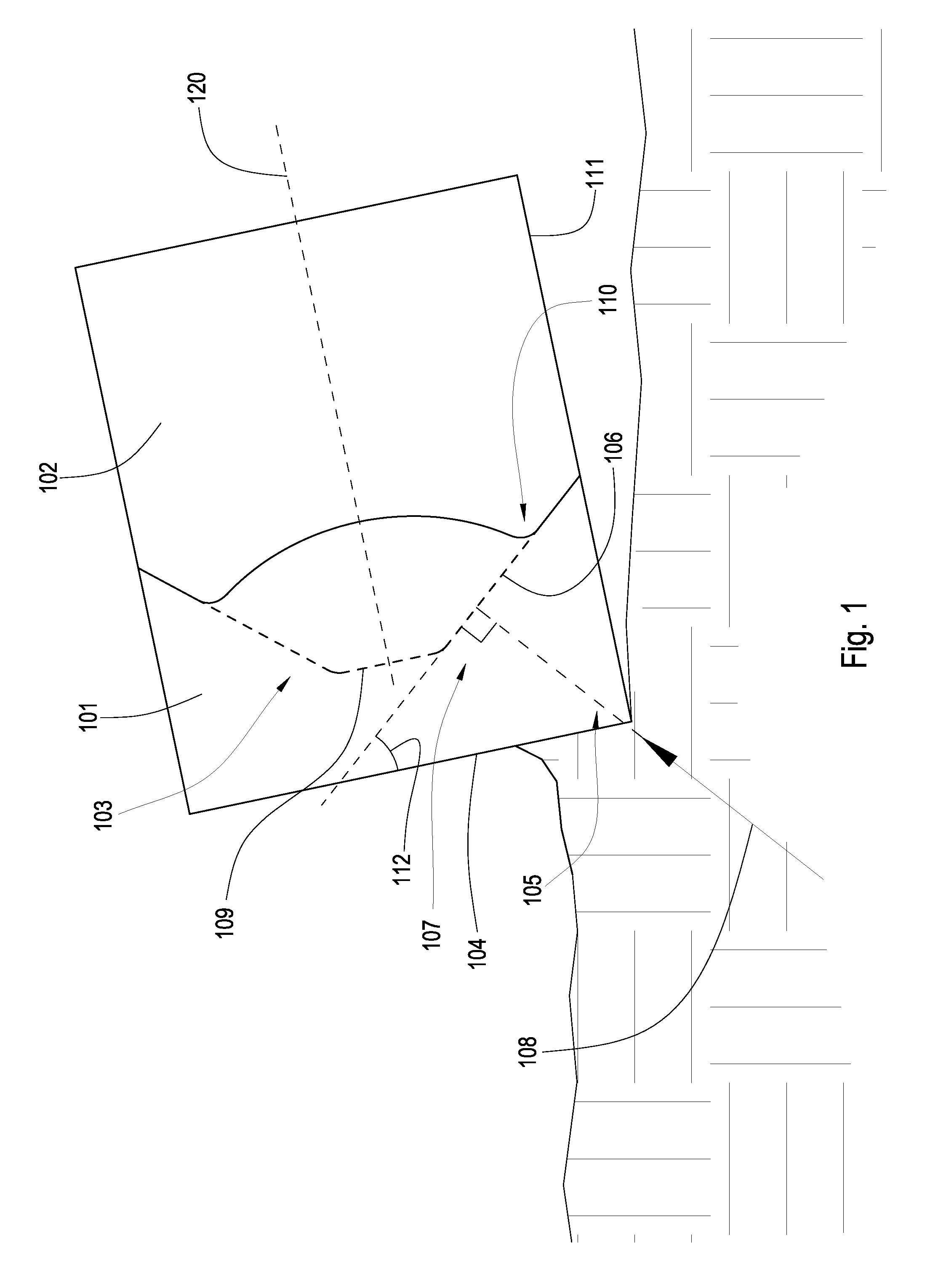
[0029]FIG. 1 discloses an embodiment of a high impact resistant tool 100 which may be used in machines in mining, downhole drilling, asphalt milling, coal mining, or trenching industries. The high impact resistant tool comprises a sintered body 101 of diamond or diamond-like particles in a metal matrix bonded to a cemented metal carbide substrate 102 at a nonplanar interface 103, a hidden portion of which is shown by the dashed line. The body 101 comprises a flat working surface 104 used to abrade or degrade road surfaces, rock and earth formations, wood, metal, or other materials.

[0030]The amount of metal in the body 101 of the high impact resistant tool 100 may be vital to the working life of the tool 100, particularly in regions near the working surface 104. At least one region 105 of the working surface 104 may be far enough away from the nonplanar interface 103 that during high pressure, high temperature (HPHT) processing a restricted amount of metal from the substrate reaches ...


PUM


Abstract

A high impact resistant tool having a sintered body of diamond or diamond-like particles in a metal matrix bonded to a cemented metal carbide substrate at a non planar interface, interface having at least two circumferentially adjacent faces, outwardly angled from a central axis of the substrate. The sintered body has a thickness of 0.100 to 0.500 inches proximate each face. The sintered body also has a flat working surface, wherein the tool has an angle of 30 to 60 degrees between the flat working surface and each face.

Description

BACKGROUND OF THE INVENTION[0001]The invention relates to a high impact resistant tool that may be used in machinery such as crushers, picks, grinding mills, roller cone bits, rotary fixed cutter bits, earth boring bits, percussion bits or impact bits, and drag bits. More particularly, the invention relates to inserts comprised of a carbide substrate with a nonplanar interface and an abrasion resistant layer of super hard material affixed thereto using a high pressure high temperature press apparatus. Such inserts typically comprise a super hard material layer or layers formed under high temperature and pressure conditions, usually in a press apparatus designed to create such conditions, cemented to a carbide substrate containing a metal binder or catalyst such as cobalt. The substrate is often softer than the super hard material to which it is bound. Some examples of super hard materials that high pressure high temperature (HPHT) presses may produce and sinter include cemented cera...

Claims


Application Information

Patent Timeline
IPC IPC(8): B24D17/00B24D99/00
CPCB24D99/005E21C35/183E21B10/567E21B10/5735
Inventor HALLCROCKETT, RONALDBAILEY, JOHNKUDLA, MATT
Owner SCHLUMBERGER TECH CORP
Why Eureka
Try Eureka