
Rotating Assembly and Its Manufacturing Method

a technology of rotating assembly and manufacturing method, which is applied in the field of rotating assembly, can solve the problems of requiring a large amount of labor, and achieve the effects of preventing deformation of the outer shape, simple method, and easy fixation on the sha

Inactive Publication Date: 2008-10-16
OTICS CORP +1
View PDF19 Cites 14 Cited by
  • Summary
  • Abstract
  • Description
  • Claims
  • Application Information

AI Technical Summary

Benefits of technology

The present invention relates to a rotating assembly and its manufacturing method. The technical effects of this invention include easy and secure fixation of a rotating member onto a shaft, reduced deformation of the rotating member, improved inspection workability, and reduced resistance during insertion. The rotating member is fixed onto the shaft by inserting the shaft into an inner hole of the rotating member and expanding the inner hole with a heating process. The shaft is then inserted into the inner hole and cooled to reduce the diameter of the inner hole again. The inner hole and the outer circumferential surface of the shaft are pressed and raised by the other part, resulting in a hook that securely fixes the rotating member onto the shaft. This hook prevents deformation of the outer shape and reduces resistance during insertion. The rotating assembly and its manufacturing method of the present invention provide a simple and effective solution for fixing the rotating member onto the shaft.

Problems solved by technology

However, it is necessary to inject a high-pressure fluid into a shaft in order to form a camshaft by the above-mentioned conventional art, which requires a large amount of labor and many processes as well as equipment such as a high-pressure fluid source, a shaft sealing apparatus or the like for the manufacture.

Method used


Image

  • Rotating Assembly and Its Manufacturing Method
  • Rotating Assembly and Its Manufacturing Method
  • Rotating Assembly and Its Manufacturing Method

Examples


embodiment 1

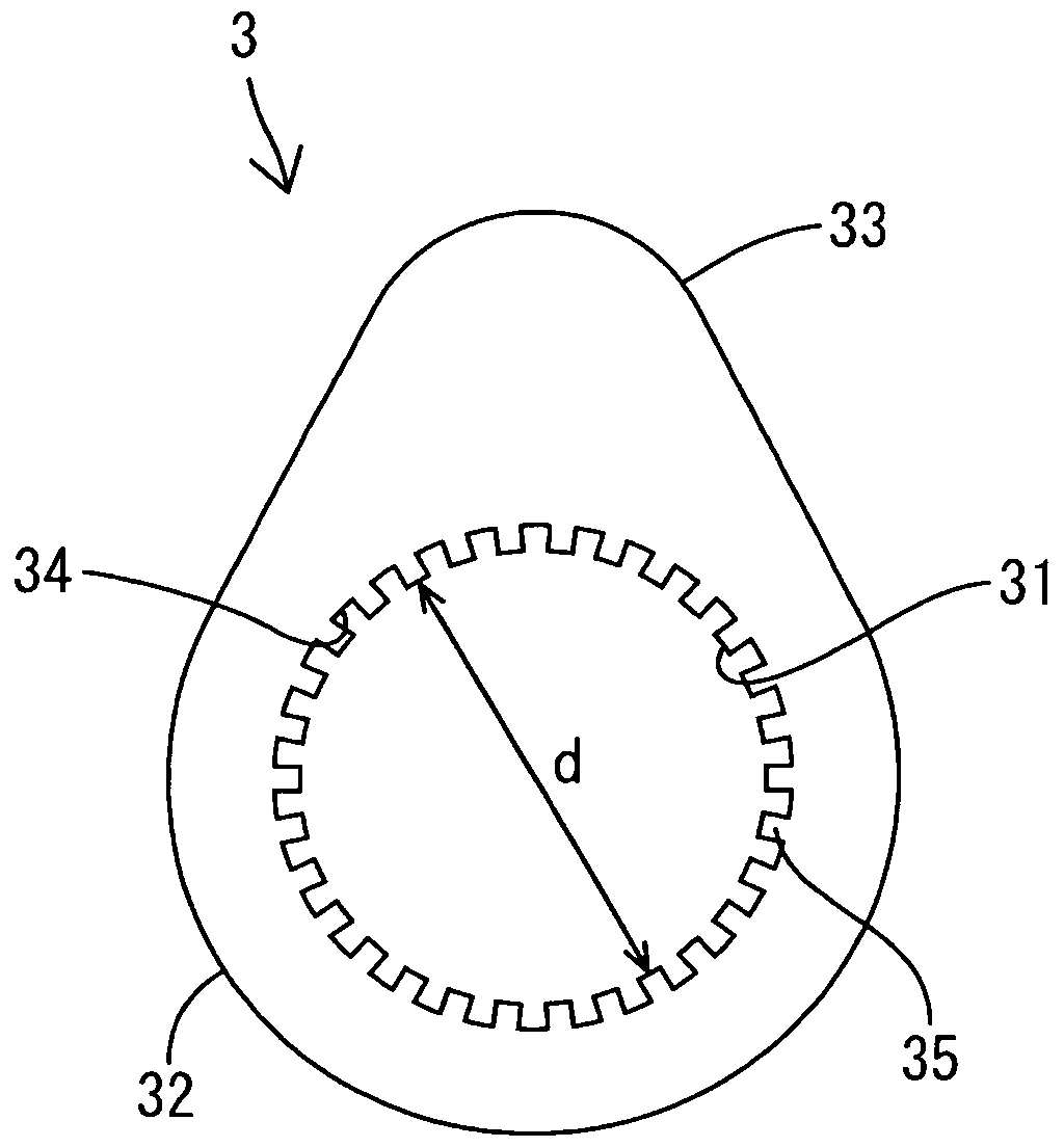
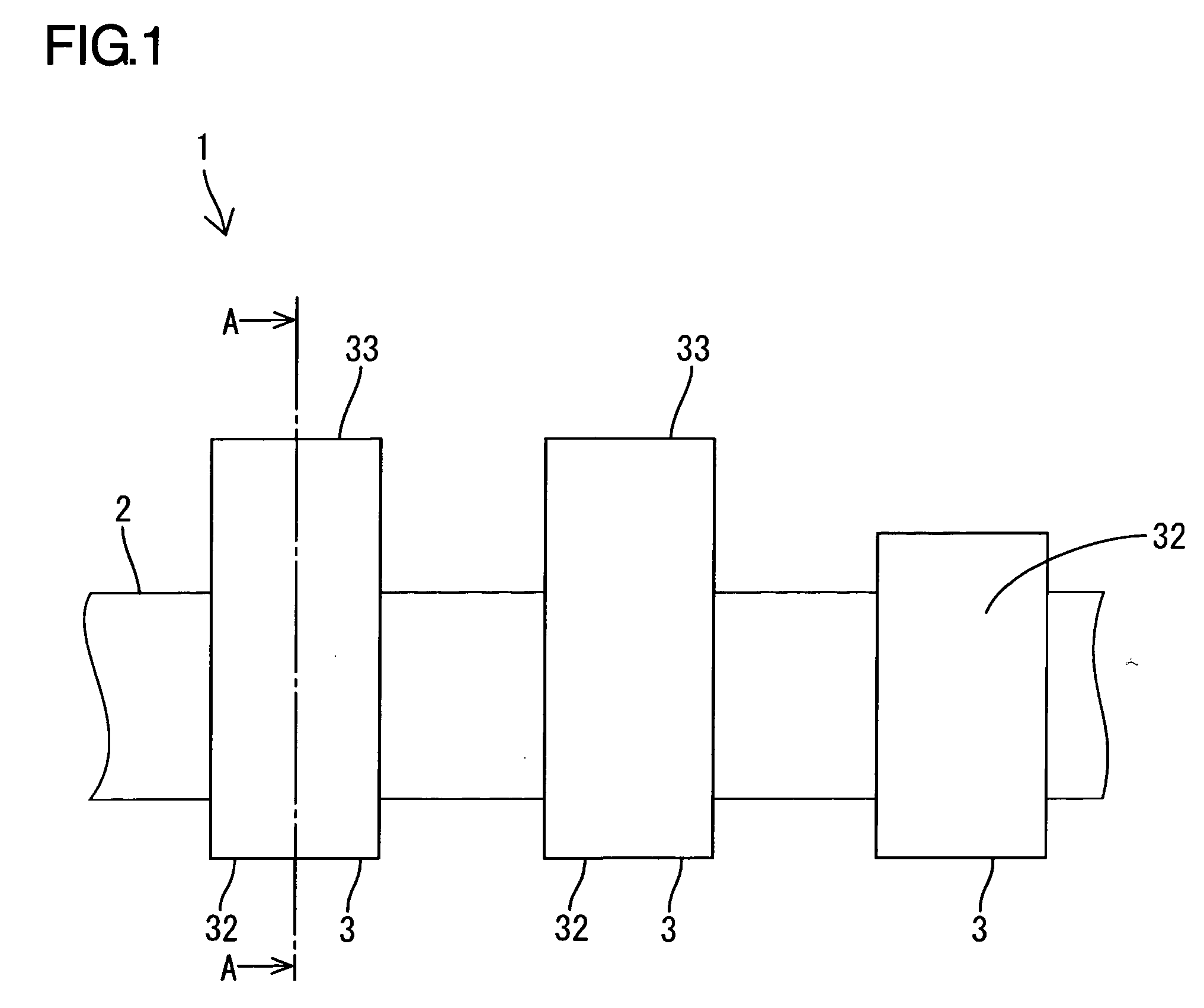
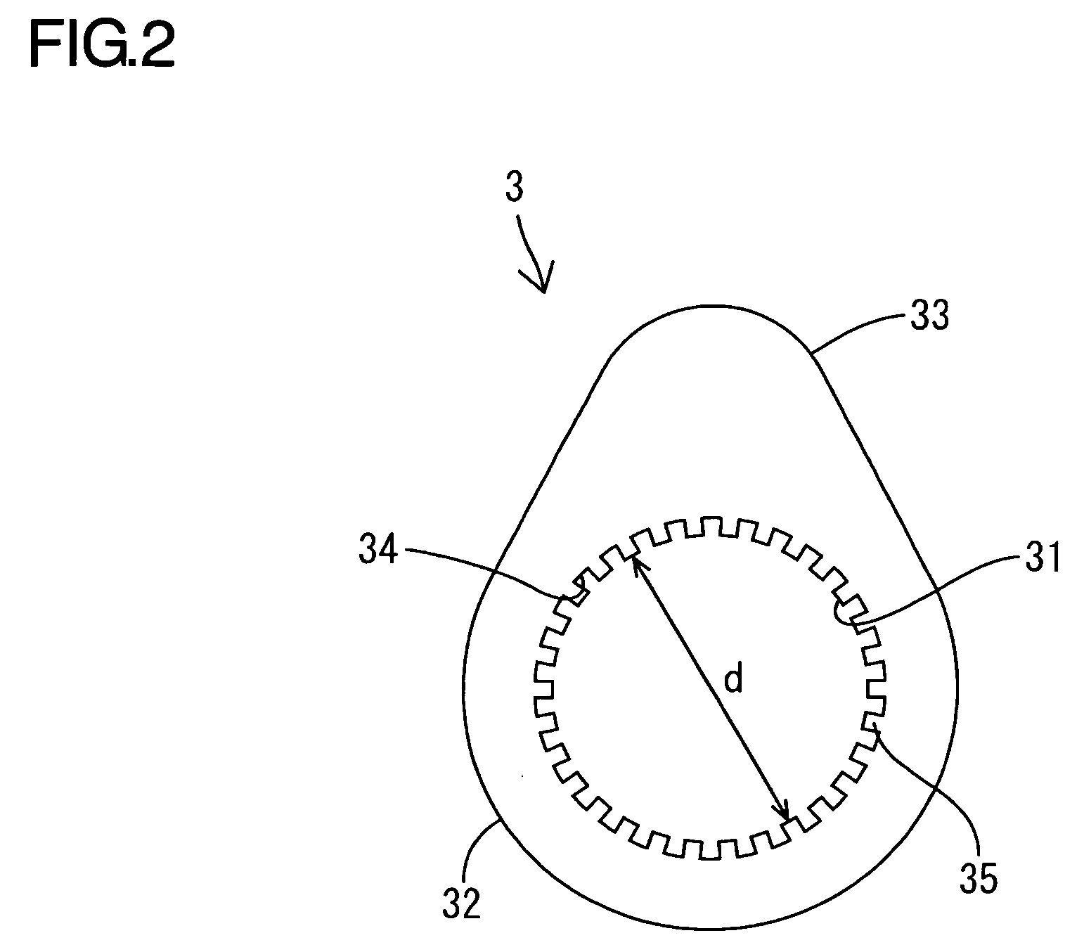
[0033]An embodiment 1 of the present invention will be described referring to FIGS. 1 to 5. As shown in FIG. 1, a camshaft 1, which is a rotating assembly according to this embodiment, has a plurality of cam pieces 3 fastened and formed on a driving shaft 2. The driving shaft 2 is formed by a pipe material made of a carbon steel or an alloy steel such as STKM material. The cam piece 3 is formed by a sintered material obtained by pressurizing and molding a metal powder of a carbon steel or an alloy steel containing Cr, V in a die and sintering it at a high temperature. As shown in FIG. 2, an inner hole 31 pierces the inside of the cam piece 3, and an inner diameter d of the inner hole 31 is formed smaller than an outer diameter of an insertion portion of the driving shaft 2. Moreover, in the cam piece 3, a circumferential-shaped outer circumferential surface 32 is formed surrounding a part of the inner hole 31, and furthermore, a camprofile 33 projecting outward is formed continuing ...

embodiment 2

[0039]Next, feature portions of an embodiment 2 of the present invention will be described referring to FIG. 6. In the inner hole 31 of a cam piece 3A according to this embodiment, a plurality of grooves 34 are formed, which is similar to embodiment 1. The grooves 34 are formed in a series at a portion located inward of the cam profile 33 (upper part of the inner hole 31 in FIG. 6) and a portion opposite thereto and located inward of the circumferential-shaped outer circumferential surface 32 (lower part of the inner hole 31 in FIG. 6), respectively. Large-diameter escape portions 37 formed by hollowing the inner hole 31 outward are provided between the series of grooves 34 formed to be opposed to each other. The pair of escape portions 37 are opposed to each other and located inward of raised portions 36, which are portions where the circumferential-shaped outer circumferential surface 32 of the cam piece 3A continues to the cam profile 33. And the portions 37 extend circumferentia...


PUM

PropertyMeasurementUnit
temperatureaaaaaaaaaa
diameteraaaaaaaaaa
outer diameteraaaaaaaaaa

Abstract

An inner hole 31 to which a driving shaft 2 is inserted is formed in a campiece 3 of a camshaft 1, and a plurality of grooves 34 extending in the insertion direction of the driving shaft 2 are formed in the inner hole 31. The driving shaft 2 is inserted into the inner hole 31 with the cam piece 3 heated to expand the diameter of the inner hole 31. By reducing again the diameter of the inner hole 31 by cooling it in this state, an outer circumferential surface of the driving shaft 2 is pressed and raised by the inner hole 31 and enters the groove 34, by which the cam piece 3 is firmly fixed onto the driving shaft 2.

Description

TECHNICAL FIELD[0001]The present invention relates to a rotating assembly in which a rotating member is fastened onto a shaft and its manufacturing method.BACKGROUND ART[0002]There is a conventional art in which an inner hole having a stepped portion is formed on a cam piece, a pipe-shaped shaft is inserted into this inner hole and then, a high-pressure fluid is injected into the shaft to expand it outward so that the shaft is accommodated in the stepped portion of the inner hole so as to fix the cam piece onto the shaft (See Patent Document 1, for example). According to this technique, a fastening strength between the cam piece and the shaft can be improved by a portion accommodated in the stepped portion of the shaft as a hook.[0003]Patent Document 1: Japanese Patent Laid-Open No. 2003-314576[0004]However, it is necessary to inject a high-pressure fluid into a shaft in order to form a camshaft by the above-mentioned conventional art, which requires a large amount of labor and many...

Claims


Application Information

Patent Timeline
Patent Type & Authority Applications(United States)
IPC IPC(8): F16H53/02B23P11/00
CPCB23P11/025B23P2700/02Y10T29/49865Y10T74/2101F16H53/025
Inventor YAMAMOTO, TAMOTSUISOGAI, EIJIKINOSHITA, KAZUMASANISHIMURA, KUNIHIROSATO, HIDEKAZU
Owner OTICS CORP
Learn More