Fuel Tank having Functions of Adjusting Press Produced by Fuel Volatilizing and Preventing Fuel Overflowing

a technology of volatilizing and fuel tank, which is applied in the field of fuel tanks, can solve the problems of fuel in the recycle pipe of the conventional fuel tank, the inner press of the fuel tank cannot be adjusted, and the fuel gas volatilizing and the route communicating with the environment are blocked, so as to prevent the overflowing of fuel, and improve the capacity of filtering the fuel gas

Inactive Publication Date: 2008-10-16
SENTEC E&E CO LTD
View PDF7 Cites 10 Cited by
  • Summary
  • Abstract
  • Description
  • Claims
  • Application Information

AI Technical Summary

Benefits of technology

[0007]An objection of the present invention is providing a fuel tank, which can adjust press produced by the fuel gas volatilizing and preventing the fuel overflowing, especially, providing a fuel tank having a double-lane valve which can respectively control two routes. The double-lane valve can cooperate with a fuel control valve and activated carbon arranged in the fuel tank for improving the capacities of filtering the fuel gas and preventing the overflowing fuel overflowing.

Problems solved by technology

However, the fuel in the route communicating with the environment and the recycle pipe of the conventional fuel tank is prone to overflow when the vehicle inclines.
However, since the route of the fuel gas volatilizing and the route communicated with the environment all pass through the fuel control valve, when the vehicle inclines, the fuel control valve is closed and the route of the fuel gas volatilizing and the route communicated with the environment are blocked such that the inner press of the fuel tank can not be adjusted.
Furthermore, there is not a predetermined press control in the route of the fuel gas volatilizing so as to increase the burthen of the canister and increase the probability of polluting the environment.

Method used


Image

  • Fuel Tank having Functions of Adjusting Press Produced by Fuel Volatilizing and Preventing Fuel Overflowing
  • Fuel Tank having Functions of Adjusting Press Produced by Fuel Volatilizing and Preventing Fuel Overflowing
  • Fuel Tank having Functions of Adjusting Press Produced by Fuel Volatilizing and Preventing Fuel Overflowing

Examples


Embodiment Construction

[0025]Reference will now be made to the drawings to describe a preferred embodiment of the present fuel tank, in detail.

[0026]Referring to FIG. 1, a fuel tank in accordance with a preferred embodiment of the present invention is shown. The fuel tank includes a fuel tank 1, a canister 4, a fuel control valve 2 and a double-lane valve.

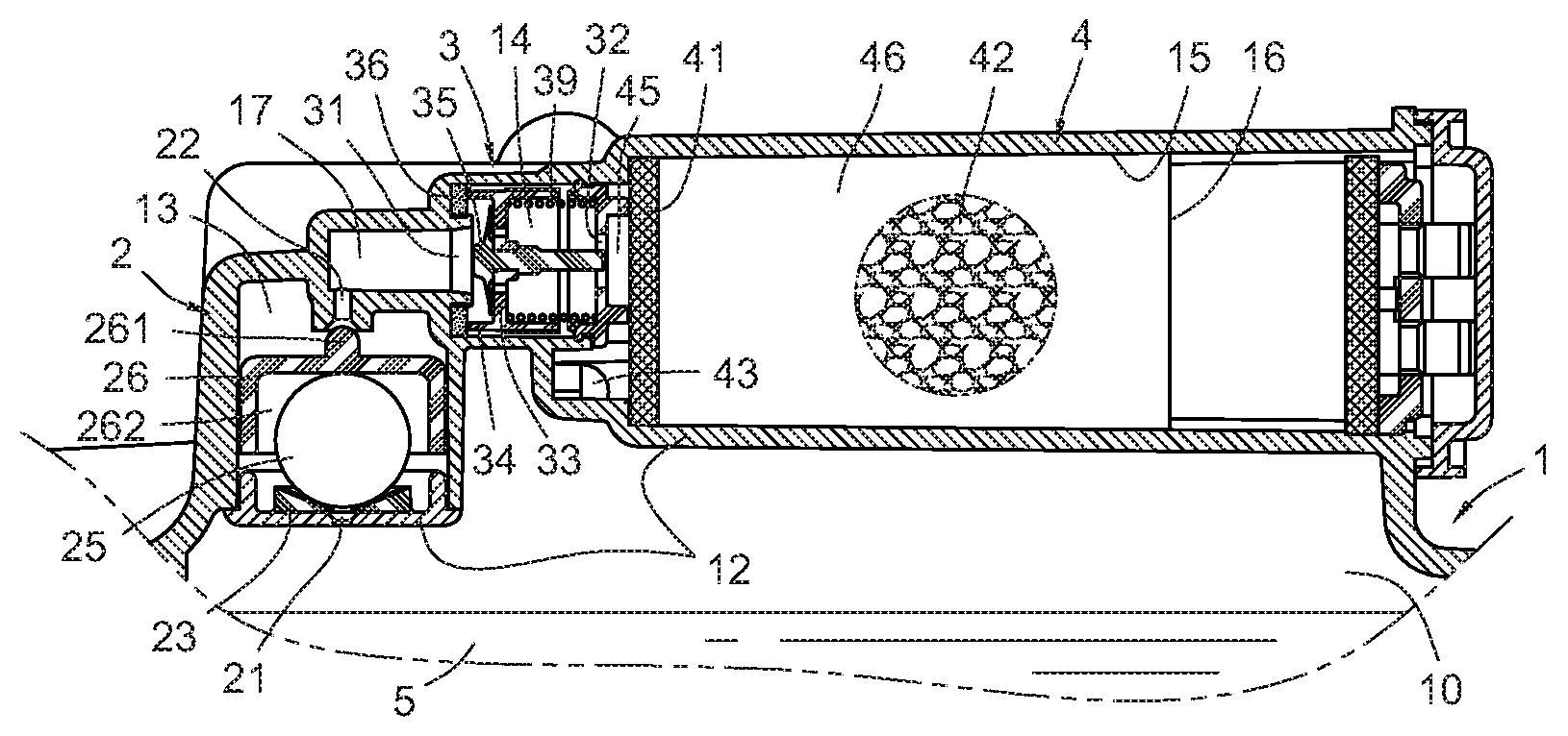
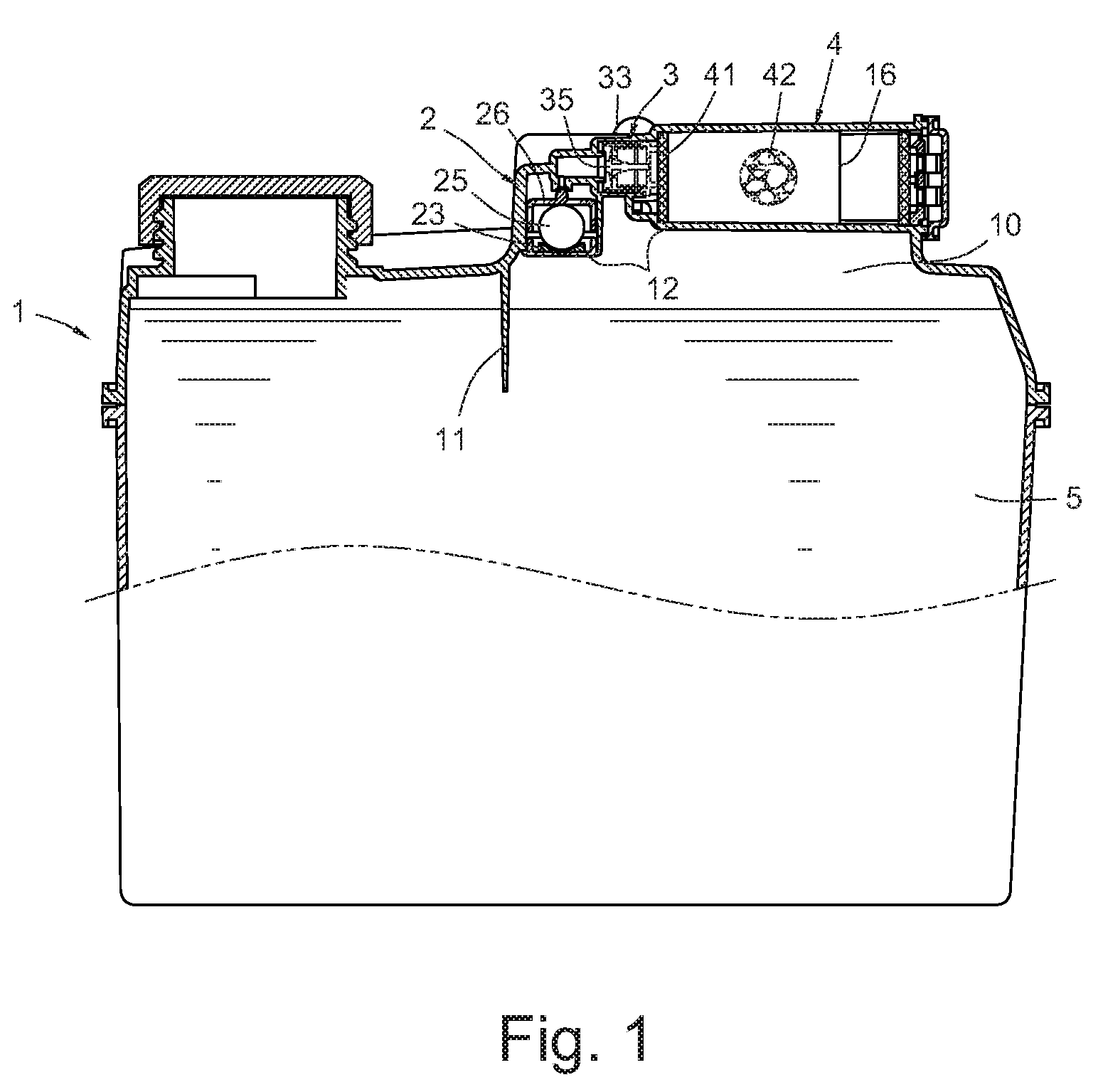
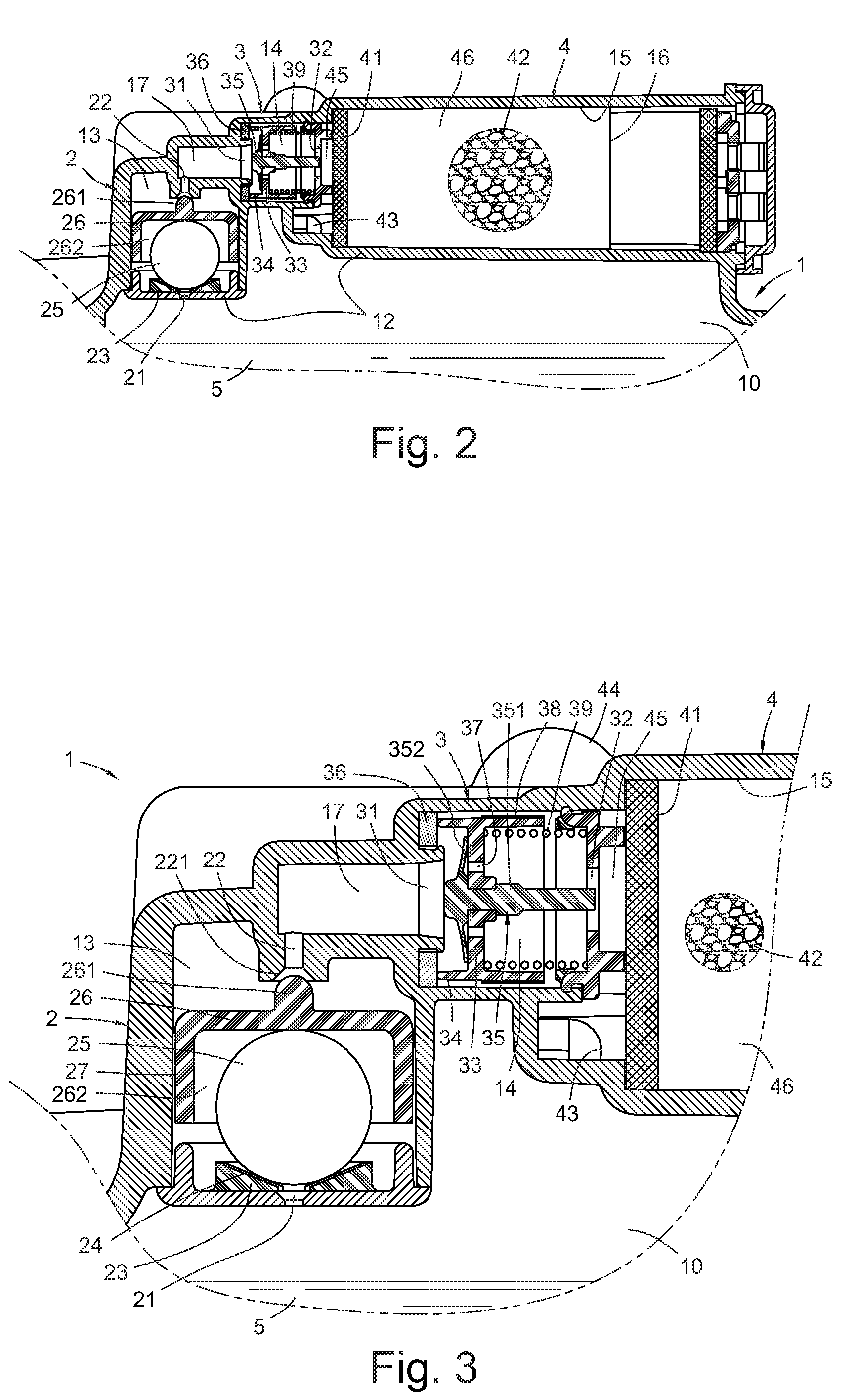
[0027]The fuel tank 1 includes an expending room 10 by using a clapboard 11 arranged in the top thereof to space fuel gas from fuel, a first valve room 13, a second valve room 14 and a chamber 15 (as shown in FIG. 3) by using a plurality of clapboard 12 (as shown in FIG. 2) arranged in the expending room 10.

[0028]The canister 4 is arranged in the chamber 15 of the expending room 10 (as shown in FIGS. 1 and 2). The canister 4 includes a plurality of sieves and activated carbon arranged therein. A fuel gas entrance 45 is formed between the chamber 15 and the second valve room 14 for guiding the fuel gas to enter. A first guiding pipe 43 (as shown in FIGS. ...


PUM


Abstract

A fuel tank includes a canister and a fuel control valve arranged in an expanding room. The canister has two guiding pipes communicated respectively with an entrance of an engine and environment. The fuel control valve is communicated with the expanding room. A double-lane valve is arranged between the canister and the fuel control valve. The double-lane valve has an entrance communicated with the fuel control valve, an exit communicated with the canister, a first valve and a second valve arranged between the entrance and the exit. The second valve withstands a spring and is arranged on the first valve. The first valve can detect an expending press produced by volatilized fuel gas to control whether the fuel gas enter into the entrance of the engine. The second valve can detects a vacuum press of the fuel tank to control whether air enter into the fuel tank.

Description

FIELD OF THE INVENTION[0001]The present invention relates to fuel tanks, and more particularly to a fuel tank mounted in a vehicle, which can adjust press produced by the fuel gas volatilizing and prevent the fuel overflowing.DESCRIPTION OF THE RELATED ART[0002]Recently, for avoiding volatilized fuel gas in a fuel tank overflowing, a canister is mounted at a route of the fuel tank communicating with the environment. The canister has a plurality of sieves and activated carbon arranged therein to filter deleterious matters of the fuel gas so as not to pollute the environment.[0003]The conventional fuel tank supplies the fuel to an engine, and the volatilized fuel gas in the fuel tank is guided into an entrance of the engine through a recycle pipe, and is reused by intermittent negative press produced in operation of the engine.[0004]However, the fuel in the route communicating with the environment and the recycle pipe of the conventional fuel tank is prone to overflow when the vehicle...

Claims


Application Information

Patent Timeline
Patent Type & Authority Applications(United States)
IPC IPC(8): F16K17/26
CPCF02M25/0836F02M25/0854F02M37/0076F16K24/042Y10T137/7771
Inventor WANG, AARONHUANG, CHUN-CHAO
Owner SENTEC E&E CO LTD
Why Eureka
Try Eureka