Disc brake pads having a visual wear indicator which signals the need for pad replacement

Inactive Publication Date: 2008-10-16
LUNDSKOG DAVID A
View PDF10 Cites 33 Cited by
  • Summary
  • Abstract
  • Description
  • Claims
  • Application Information

AI Technical Summary

Benefits of technology

[0005]The present invention provides a new method and apparatus for signaling to an inspector on a cursory exterior examination of a vehicle that brake pads have reached the limit of safe wear. An advantage with the present invention is that is compatible with and can be used in combination with the prior art methods and apparatus discussed in the Background section above. Brake pads made in accor

Problems solved by technology

However, as the friction lining wears, the

Method used


Image

  • Disc brake pads having a visual wear indicator which signals the need for pad replacement
  • Disc brake pads having a visual wear indicator which signals the need for pad replacement
  • Disc brake pads having a visual wear indicator which signals the need for pad replacement

Examples


Embodiment Construction

[0020]The invention will now be described with reference to the attached drawing FIGS. 1 to 10. It should be understood that the drawing figures are not necessarily drawn to scale and are meant to be merely illustrative of the invention.

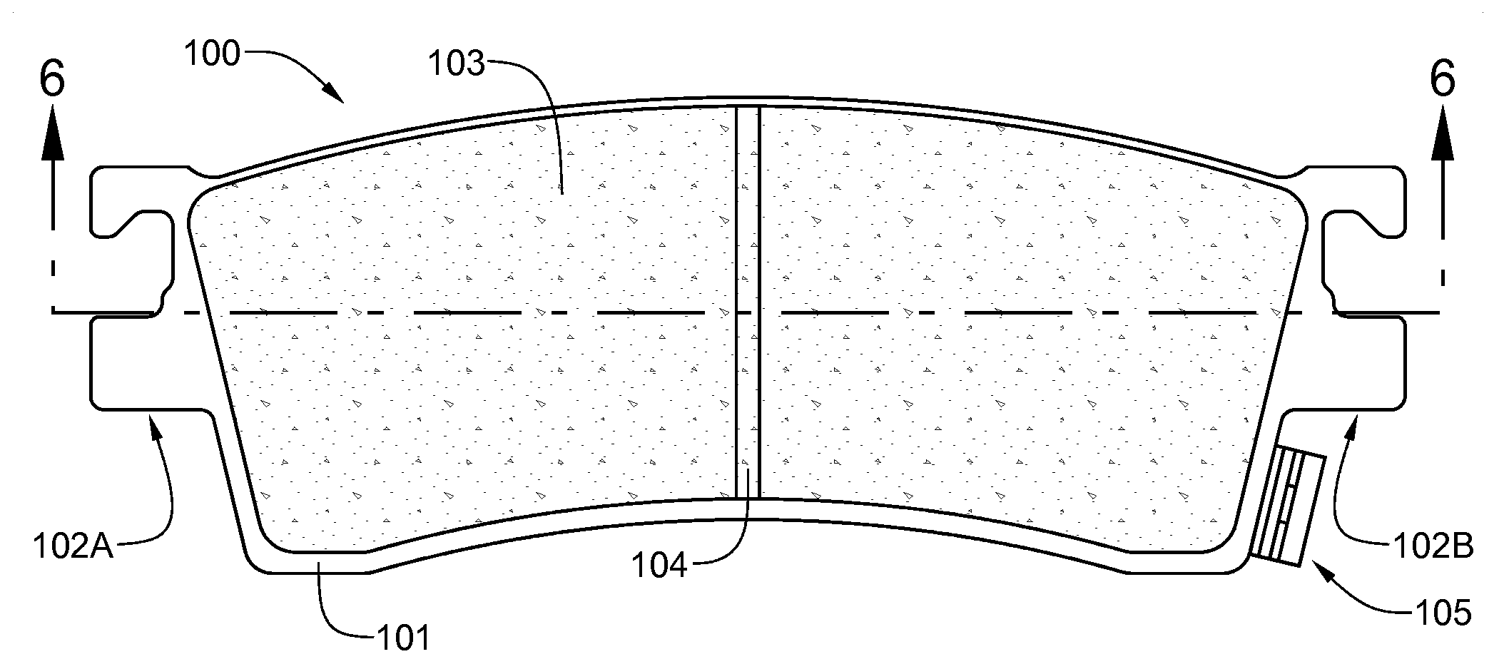
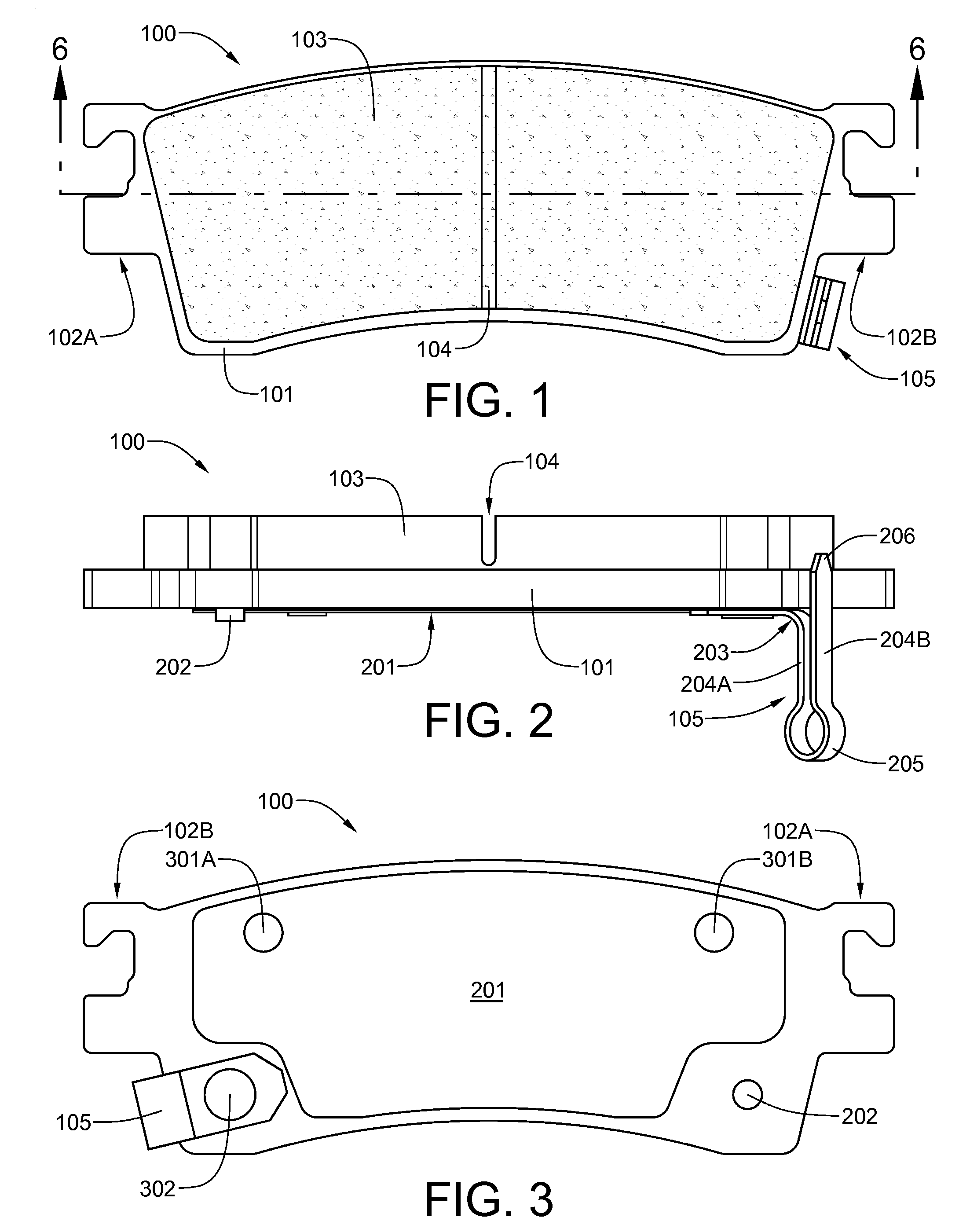
[0021]Referring now to FIG. 1, the brake pad 100 includes: a backing plate 101 with brake caliper attachment ears 102A and 102B; a friction lining 103 having a central groove 104, which reduces the likelihood of the lining cracking when hot and also reduces wear on a brake rotor by capturing highly-abrasive particles such as sand at a halfway location on the pad so that they do not traverse the entire length of the pad; and a noise-making friction lining wear indicator bracket 105. All of the features visible in this view of the FIG. 1 brake pad 100 are prior art features; features related to the present invention will be seen in other views.

[0022]Referring now to FIG. 2, the brake pad 100 of FIG. 1 further includes a shim plate 201 that is riveted t...


PUM


Abstract

A new method and apparatus signals to an inspector on a cursory exterior examination of a vehicle that brake pads have reached the limit of safe wear. Brake pads are designed to release a material that has a color other than the browns and grays of conventional brake pad dust when they reach the limit of safe wear. The colored material distributes itself on the wheel of the vehicle, thereby offering telltale evidence of worn-out brake pads. A first embodiment brake pad employs a colored powdered material enclosed in at least one pocket beneath the normal wear range of the friction lining. A third embodiment brake pad employs a heat-stable, colored liquid or slurry in metal capsule. The capsule is breached by rubbing against the brake rotor when the wear limit is reached. Inorganic pigments are used for powder, slurry and friction lining colorants.

Description

FIELD OF THE INVENTION[0001]This invention relates, generally, to a brake pads for vehicle disc brakes, the pad comprising a backing plate and a friction lining. More particularly, the invention relates to wear indicators which are incorporated into the brake pads, and are designed to alert the driver of a vehicle when the pads need replacing.BACKGROUND OF THE INVENTION[0002]Several approaches have been used in the past to prevent damage to disc brake rotors when the friction lining on the brake pad backing plate is nearly worn away. In the 1960's, Daimler Benz Corporation fitted its vehicles with disc brake calipers having soft, fast-wearing friction linings that generated very little wear on the rotors. It was a fairly simple job to replace the brake pads, as the rotors seldom needed turning or replacement. However, to prevent the brake pad backing plates from scoring the rotor when the friction linings wore out, each disc brake caliper was fitted with a spacer that prevented the ...

Claims


Application Information

Patent Timeline
IPC IPC(8): F16D66/02
CPCF16D65/092
Inventor LUNDSKOG, DAVID A.
Owner LUNDSKOG DAVID A
Why Eureka
Try Eureka