Switch device

a technology of switch and switch body, which is applied in the direction of emergency contact, emergency protective device, contacts, etc., can solve the problems of inability to securely detect the on-state state, the contact failure between the second and third contact portions and the first contact portions is more likely to occur,

Inactive Publication Date: 2008-10-16
KK TOKAI RIKA DENKI SEISAKUSHO
View PDF4 Cites 40 Cited by
  • Summary
  • Abstract
  • Description
  • Claims
  • Application Information

AI Technical Summary

Benefits of technology

[0013]Therefore, it is an object of the invention to provide a switch device, by which it is possible to electrically conduct between the second and third contact portions while allowing a displacement of the first contact portion when detecting the ON-state, thereby securely detecting the ON-state.
[0030]According to present invention, it is possible to electrically conduct between the second third contact portions while allowing the displacement of the first contact portion when detecting the ON-state, thereby securely providing the ON-state of the switch device.

Problems solved by technology

Therefore, if the dislocation direction of the first contact portion is shifted in the direction parallel to the second and third contact portions, a contact failure between one of the second and third contact portions and the first contact portion is more likely to occur.
As a result, there was a problem in that the second and third contact portions are not electrically conducted when detecting the ON-state and it is not possible to securely detect the ON-state.

Method used


Image

  • Switch device
  • Switch device
  • Switch device

Examples


embodiment

Preferred Embodiment

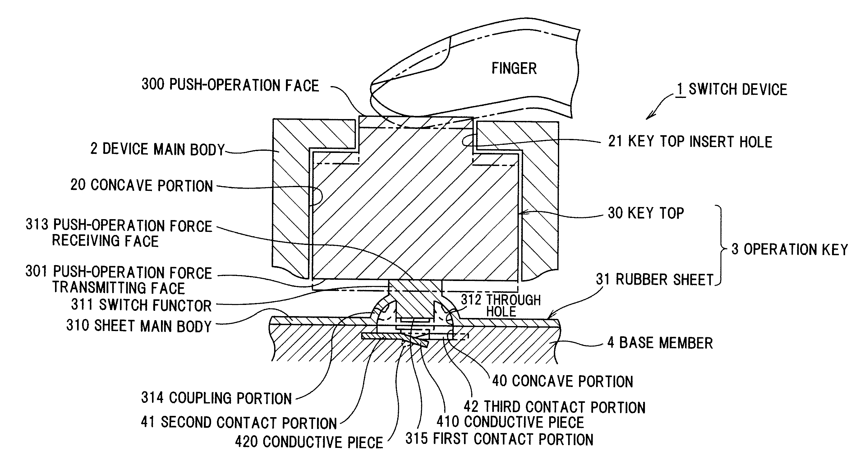
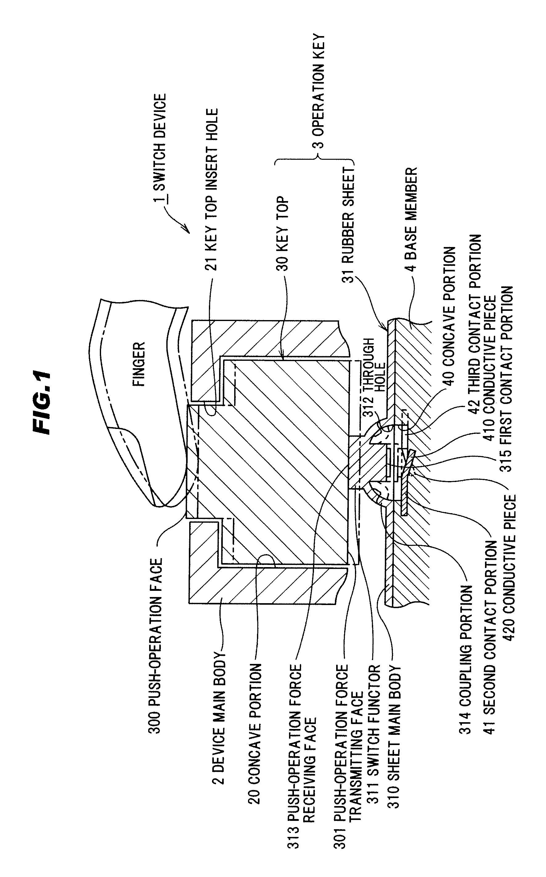
[0036]FIG. 1 is an explanatory diagram showing a cross section of a total structure of a switch device in a preferred embodiment according to the present invention.

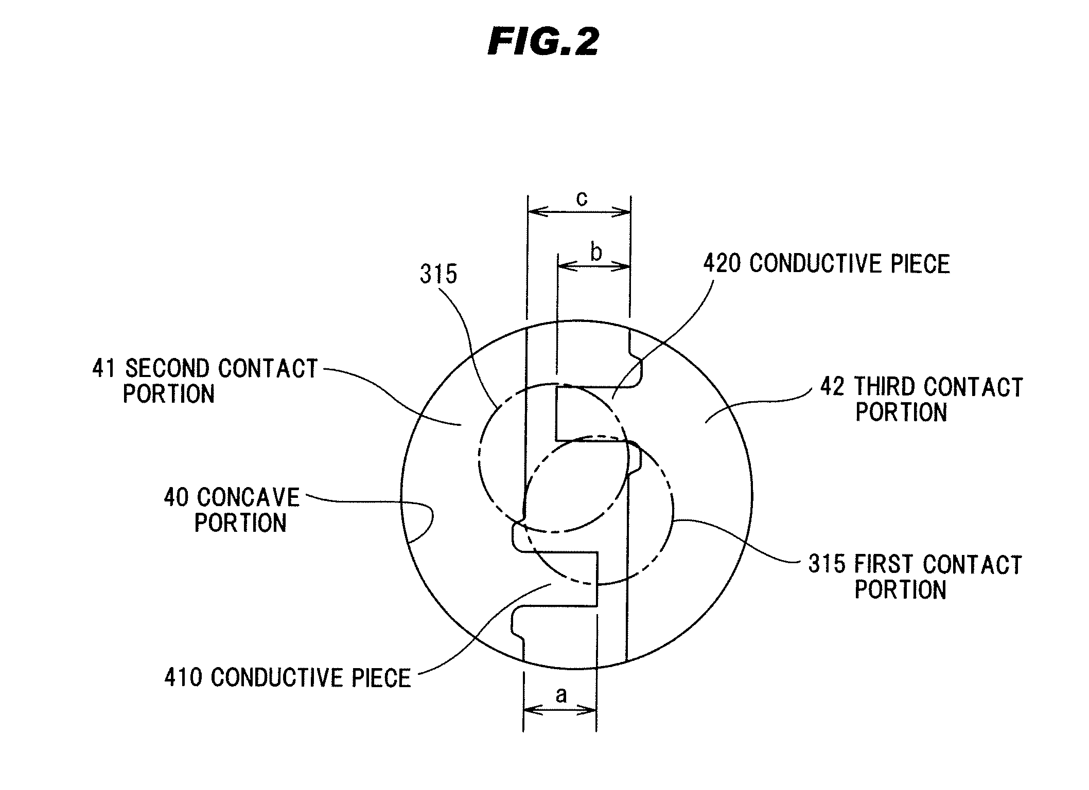
[0037]FIG. 2 is an explanatory plan view of a main section of the switch device in the preferred embodiment according to the present invention.

[0038]FIG. 3 is an explanatory diagram showing an enlarged cross section of the main section of the switch device in the preferred embodiment according to the present invention.

[0039](Total Structure of a Switch Device)

[0040]In FIG. 1, a switch device 1 comprises a device main body 2, an operation key 3 as a push switch member, and a base member 4 for detecting a push operation state of the operation key 3.

[0041](Structure of the Device Main Body 2)

[0042]As shown in FIG. 1, the device main body 2 comprises a concave portion 20 that is opened downwards, and a key top insert hole 21 opened inside and outside of the concave portion 20. The device main body 2 compri...


PUM


Abstract

A switch device is provided with an operation key 3 having a first contact portion 315. The operation key 3 is dislocated in a push direction by a push operation. A base member 4 has a second contact portion 41 and a third contact portion 42 electrically conducted by a contact with a first contact portion 315 by the dislocation of the operation key 3 in the push direction. In the base member 4, the second contact portion 41 and the third contact portion 42 are arranged in parallel to each other. A conductive piece 410 projecting toward a third contact portion 42 is connected to the second contact portion 41, and a tip portion of the conductive piece 410 is embedded in the base member 4. A conductive piece 420 projecting toward the second contact portion 41 is connected to the third contact portion 42, and a tip portion of the conductive piece 420 is embedded in the base member 4.

Description

[0001]The present application is based on Japanese Patent Application No. 2007-107174 filed on Apr. 16, 2007, the entire contents of which are incorporated herein by reference.BACKGROUND OF THE INVENTION[0002]1. Field of the Invention[0003]The present invention relates to a switch device, in more particular, to a switch device provided with a switch operation member (push switch member) to be turned ON (ON-state) by a push operation.[0004]2. Related Art[0005]As one example of conventional switch devices, JP-A-9-92073 discloses a switch device which detects an operation state when, for example, a push operation of a push switch member is conducted by an operator.[0006]The conventional switch device disclosed by JP-A-9-92073 comprises a case having a key top insert hole opened inside and outside of the case, an elastically deformable rubber sheet having a key top as a push switch member penetrating movable into the key top insert hole of the case, and a printed circuit board having a ...

Claims


Application Information

Patent Timeline
Patent Type & Authority Applications(United States)
IPC IPC(8): H01H1/14
CPCH01H13/79H01H2203/038H01H2203/056H01H2239/03
Inventor AOKI, WATARU
Owner KK TOKAI RIKA DENKI SEISAKUSHO
Why Eureka
Try Eureka