Powered surgical instrument

a surgical instrument and power technology, applied in the field of surgical instruments, can solve the problems of user exerting a significant force on the operation handle and knob

Active Publication Date: 2008-10-16
TYCO HEALTHCARE GRP LP
View PDF99 Cites 644 Cited by
  • Summary
  • Abstract
  • Description
  • Claims
  • Application Information

AI Technical Summary

Benefits of technology

[0028]In certain preferred embodiments, a user interface including at least one switch that controls the translation of the rod is included. At least a portion of the rod is desirably disposed at least partially within the drive tube. In certain embodiments, the drive tube includes a threaded portion on an interior surface thereof. The r...

Problems solved by technology

Such surgical instruments can require the user to exert a significant force in oper...

Method used


Image

  • Powered surgical instrument
  • Powered surgical instrument
  • Powered surgical instrument

Examples


Embodiment Construction

[0043]Embodiments of the presently disclosed powered surgical instrument are now described in detail with reference to the drawings, in which like reference numerals designate identical or corresponding elements in each of the several views. As used herein the term “distal” refers to that portion of the powered surgical instrument, or component thereof, farther from the user while the term “proximal” refers to that portion of the powered surgical instrument or component thereof, closer to the user.

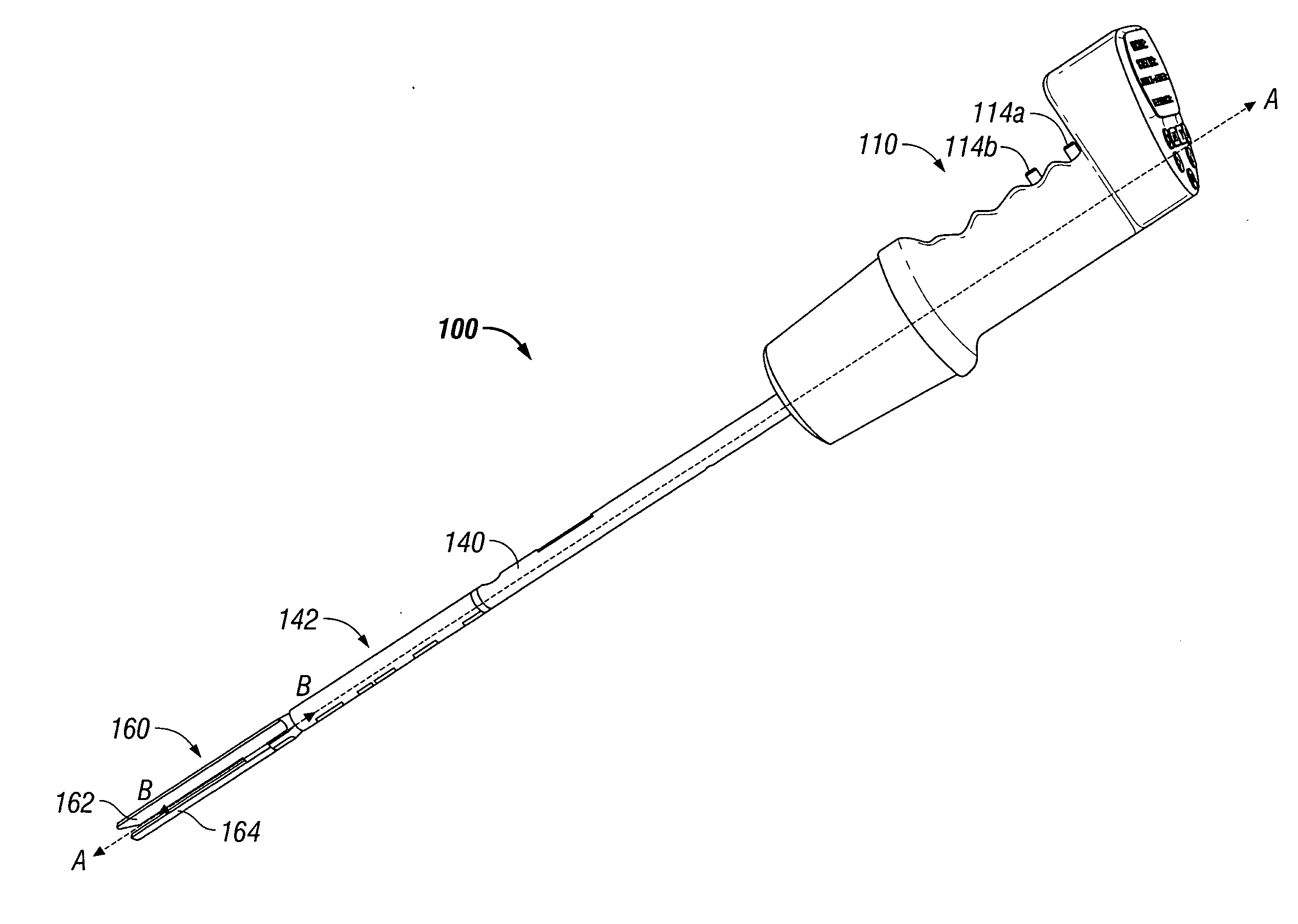
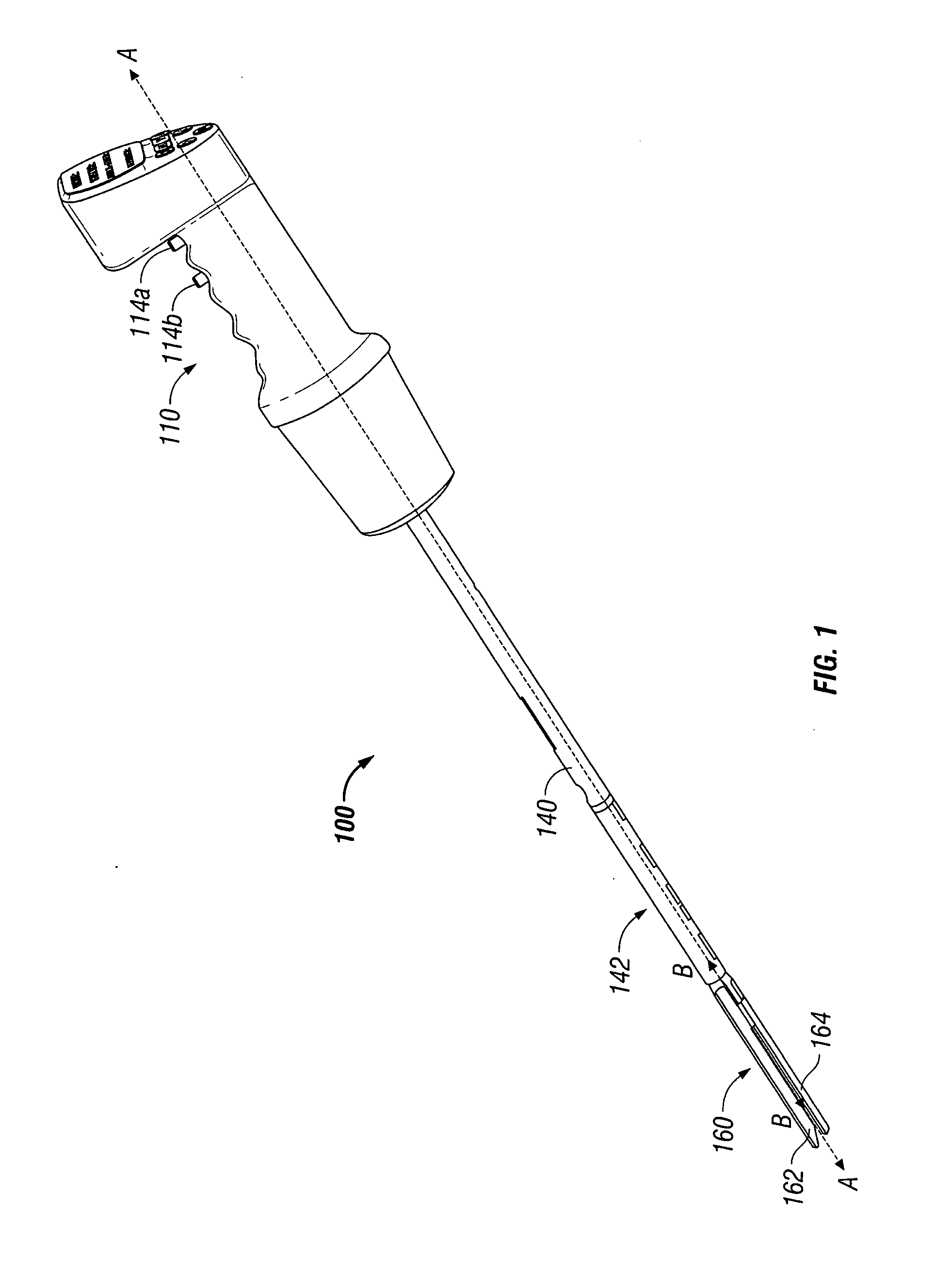
[0044]A powered surgical instrument, e.g., a surgical stapler, in accordance with the present disclosure is referred to in the figures as reference numeral 100. Referring initially to FIG. 1, powered surgical instrument 100 includes a housing 110, an endoscopic portion 140 defining a longitudinal axis A-A extending therethrough, and an end effector 160, defining a longitudinal axis B-B (illustrated substantially aligned with axis A-A in FIG. 1) extending therethrough. Endoscopic portion 14...


PUM

PropertyMeasurementUnit
Angleaaaaaaaaaa
Poweraaaaaaaaaa
Speedaaaaaaaaaa

Abstract

A surgical instrument including a housing, an endoscopic portion, a drive gear, a drive motor, a shift motor and an end effector is disclosed. The endoscopic portion extends distally from the housing and defines a longitudinal axis. The drive gear is disposed at least partially within the housing and is rotatable about a drive gear axis which extends therethrough. The drive gear is selectively movable along the drive gear axis. The drive motor is disposed in mechanical cooperation with the drive gear and is configured to rotate the drive gear. The shift motor is disposed in mechanical cooperation with the drive gear and is configured to move the drive gear along the drive gear axis. The end effector is disposed adjacent a distal portion of the endoscopic portion.

Description

BACKGROUND[0001]1. Technical Field[0002]The present disclosure relates to surgical instruments for fastening body tissue and, more particularly, to a powered surgical instrument having a drive gear configured to be movable to affect rotation, articulation and actuation of the instrument.[0003]2. Background of Related Art[0004]Surgical devices wherein tissue is first grasped or clamped between opposing jaw structure and then joined by surgical fasteners are well known in the art. In some instruments, a knife is provided to cut the tissue which has been joined by the fasteners. The fasteners typically include surgical staples and two part polymeric fasteners.[0005]Instruments for this purpose may include two elongated members which are respectively used to capture or clamp tissue. Typically, one of the members carries a staple cartridge that houses a plurality of staples arranged in rows while the other member has an anvil that defines a surface for forming the staple legs as the stap...

Claims


Application Information

Patent Timeline
IPC IPC(8): A61B17/00A61B1/00A61B17/32A61B18/18A61B1/04
CPCA61B17/068A61B17/072A61B2017/00199A61B17/00234A61B2017/00734A61B2017/2905A61B2017/00398A61B17/07207A61B2090/065A61B90/98A61B2017/00017A61B2017/00026A61B2017/00084A61B2017/00115
Inventor ZEMLOK, MICHAELRACENET, DAVID C.
Owner TYCO HEALTHCARE GRP LP
Why Eureka
Try Eureka