Composite spring with resilient attachment interface

a technology of resilient attachment and composite spring, which is applied in the field of composite springs, can solve the problems of unsatisfactory utilization of this type of bracket and mounting configuration, and achieve the effects of increasing fore and aft strength, increasing lateral stiffness, and increasing lateral stiffness

Inactive Publication Date: 2008-10-16
ARVINMERITOR TECH
View PDF33 Cites 29 Cited by
  • Summary
  • Abstract
  • Description
  • Claims
  • Application Information

AI Technical Summary

Benefits of technology

[0007]In one disclosed embodiment, two rubber blocks are used, one rubber block being bonded to an upper surface of the composite spring and one rubber block being bonded to a lower surface of the composite spring. In one example, a rigid plate is then bonded to each outwardly facing surface of the rubber blocks and fasteners are inserted through the rigid plates, rubber blocks, and composite spring to secure the composite spring to a vehicle structure. An additional rigid plate or plates may be molded within the rubber blocks to increase lateral stiffness as needed.
[0008]In one disclosed embodiment, the resilient element comprises a bushing that is inserted through a thickness of at least one of the first and second ends. The at least one of the first and second ends is curved upwardly such that the bushing extends in a generally longitudinal direction. Two longitudinally extending bushings could be used to increase lateral stiffness as needed. Optionally, the bushing may include an internal ball joint to increase fore and aft strength as needed.
[0009]By attaching resilient elements to ends of the composite spring, it is easier to mount the composite spring to a vehicle structure. Further, this attachment interface reduces the amount of additional attachment hardware that is needed to secure the composite springs to the vehicle structure, which correspondingly reduces weight and cost.

Problems solved by technology

Utilizing this type of bracket and mounting configuration is not ideal from a cost and material standpoint.

Method used


Image

  • Composite spring with resilient attachment interface
  • Composite spring with resilient attachment interface
  • Composite spring with resilient attachment interface

Examples


Embodiment Construction

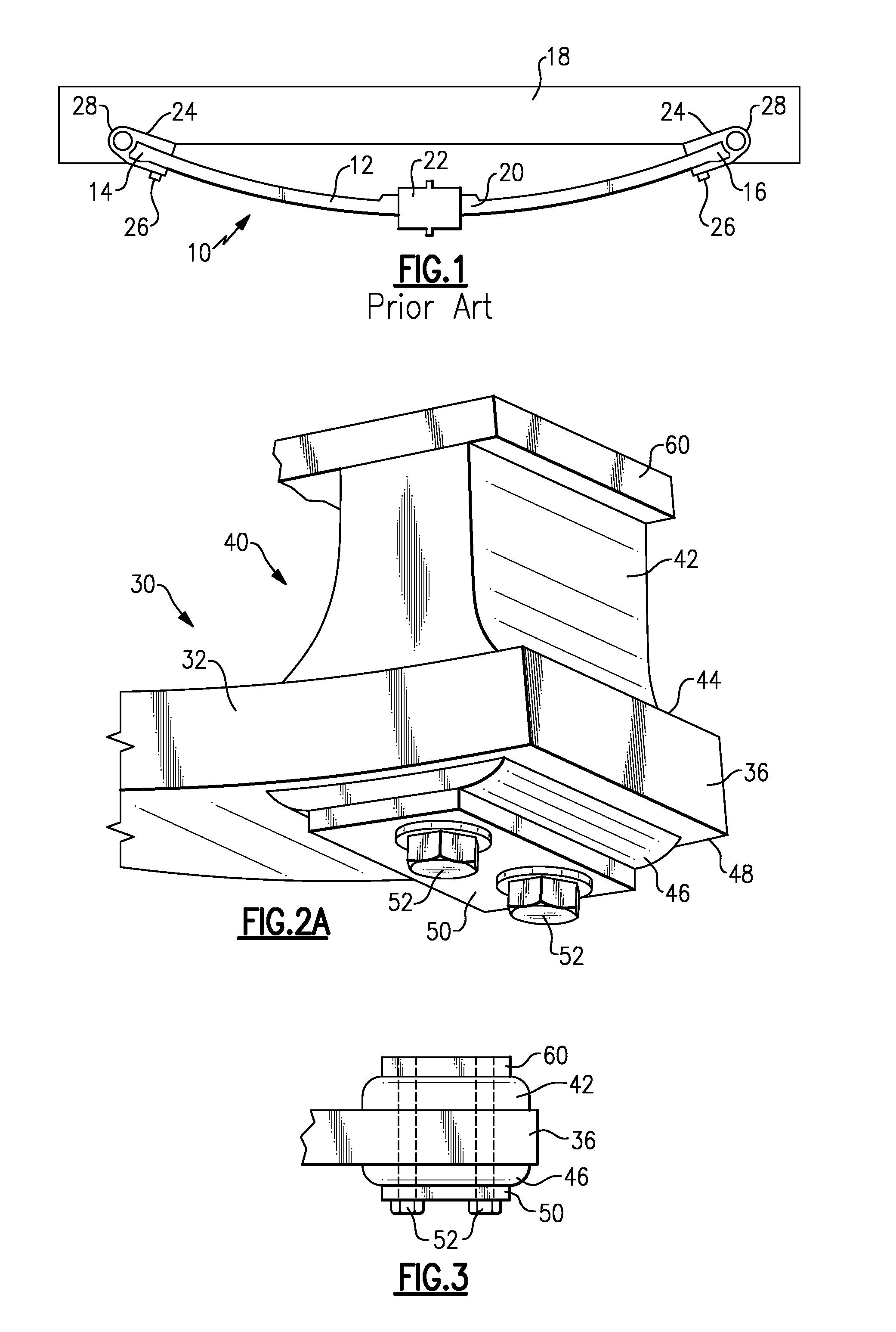
[0020]A leaf spring assembly 10 designed according to the prior art is shown in FIG. 1. The leaf spring assembly 10 includes one or more elongate spring bodies 12 formed from a composite material that includes first 14 and second 16 ends that are mountable to a vehicle structure 18, such as a frame member for example. A center portion 20 of the spring body 12 is mounted to an axle (not shown) with a mounting component 22, such as a plate and fastener assembly. The spring body 12 extends in a longitudinal direction along a vehicle length and the axle extends along a lateral direction across a vehicle width.

[0021]Each of the first 14 and second 16 ends includes an extruded aluminum component 24 that is mechanically attached to the spring body 12 with fasteners 26. Each extruded aluminum component 24 includes a circular boss portion 28 with a bore that receives a bushing to pivotally mount the first 14 and second 16 ends to the vehicle structure 18. The use of the extruded aluminum com...


PUM

PropertyMeasurementUnit
resilientaaaaaaaaaa
lateral stiffnessaaaaaaaaaa
thicknessaaaaaaaaaa

Abstract

A leaf spring for a vehicle suspension is formed from a composite material and includes first and second ends that are longitudinally spaced apart from each other. A resilient element is attached to at least one of the first and second ends. The resilient element includes at least one hole that receives a connecting element. The resilient element and the connecting element cooperate to attach the leaf spring to a vehicle structure. In one example, the resilient element comprises a rubber block that is bonded to the leaf spring. In another example, the resilient element comprises a longitudinally orientated bushing that is inserted through a thickness of the leaf spring.

Description

TECHNICAL FIELD[0001]The subject invention relates to a composite spring for a vehicle suspension with a resilient attachment interface for securing the composite spring to a vehicle structure.BACKGROUND OF THE INVENTION[0002]Vehicle suspensions include springs that cooperate with other suspension components to improve ride and handling characteristics for a vehicle. One type of spring used in vehicle suspensions is a composite leaf spring. The composite leaf spring extends in a longitudinal direction and has first and second ends that are pivotally mounted to a vehicle frame. A center portion of the composite leaf spring is supported by an axle component, which extends in a lateral direction across a width of the vehicle.[0003]Each of the first and second ends of the composite leaf spring includes a metal bracket. Traditionally, each metal bracket comprises an aluminum extrusion that is mechanically fastened to the composite leaf spring. The metal bracket is configured to receive a...

Claims


Application Information

Patent Timeline
Patent Type & Authority Applications(United States)
IPC IPC(8): B60G11/00B60G11/34
CPCB60G11/10B60G2202/112B60G2204/121F16F1/3686
Inventor PLATNER, DAVID K.WEBER, ARNETT R.SOMNAY, RAJESH J.GIANGRANDE, HOLLY ANNVARELA, TOMAZ DOPICOKNOUFF, BRIAN J.REINECK, BENJAMIN R.AUSTIN, NORMAN D.MUTZNER, JOHN E.
Owner ARVINMERITOR TECH
Why Eureka
Try Eureka