Steering Device

a steering device and steering column technology, applied in the direction of steering column, steering parts, vehicle components, etc., can solve the problems of high cost of parts, high cost of materials, and difficulty in improving the supporting rigidity of so as to improve the supporting rigidity of the outer column to the vehicle body attaching bracket, the effect of reducing weight and improving the fastening force of the outer column to the inner column

Active Publication Date: 2008-10-16
NSK LTD
View PDF8 Cites 54 Cited by
  • Summary
  • Abstract
  • Description
  • Claims
  • Application Information

AI Technical Summary

Benefits of technology

[0069]In the steering device of the present invention, the right and left side surfaces of the outer column include the first abutting surfaces that can abut on the inner surfaces of the side plates of the vehicle body attaching bracket in the vicinity of the axis of the fastening rod, the second abutting surfaces that can abut on the inner surfaces of the side plates of the vehicle body attaching bracket in the vicinity of the axis of the outer column, and recessed parts respectively formed between the abutting surfaces and more recessed than the abutting surfaces.
[0070]Accordingly, the number of parts or the number of assembling processes is not increased, a fastening force of the outer column to the inner column is improved and the supporting rigidity of the outer column to the vehicle body attaching bracket can be improved.
[0071]Further, the steering device of the present invention includes the abutting surfaces that are formed in the right and left side surfaces of the column and can abut on the inner surfaces of the side plates of the vehicle body attaching bracket in the vicinity of the axis of the fastening rod and the abutting surfaces that are formed in the right and left side surfaces of the column, have a width equal or larger than the horizontal width of the abutting surfaces in the vicinity of the fastening rod and can abut on the inner surfaces of the side plates of the vehicle body attaching bracket in a position spaced upward from the axis of the fastening rod in the vehicle body.
[0072]Further, the steering device of the present invention includes abutting surfaces that are formed in the inner surfaces of the right and left side plates of the vehicle attaching bracket and can abut on the right and left side surfaces of the column in the vicinity of the axis of the fastening rod and abutting surfaces that are formed in the inner surfaces of the right and left side plates of the vehicle body attaching bracket, have a width smaller than the horizontal width of the abutting surfaces in the vicinity of the axis of the fastening rod and can abut on the right and left side surfaces of the column in a position spaced upward from the axis of the fastening rod in the vehicle body.
[0073]Accordingly, the inner surfaces of the right and left side plates of the vehicle body attaching bracket abut on the right and left side surfaces of the column at both the position in the vicinity of the axis of the fastening rod and the position spaced upward from the axis of the fastening rod in the vehicle body to fasten the column. Therefore, the number of parts or the number of assembling processes is not increased, a weight is decreased and the supporting rigidity of the column to a vehicle body attaching bracket can be improved.

Problems solved by technology

In order to improve the supporting rigidity of the vehicle body attaching bracket, the vehicle body attaching bracket may be reinforced, however, a problem arises that the cost of a material is high and a weight increases.
However, since there is a dimensional unevenness in production, the fastening position of the side plates 32A and 32B of the vehicle body attaching bracket 3 and the outer column 1 is limited to a part in the vicinity of the axis of the fastening rod 34.
Thus, it is difficult to improve the supporting rigidity of the vehicle body attaching bracket 3.
However, in the steering device disclosed in the Patent Document 2, since the number of parts is increased, a problem arises that the cost of the parts is high and the number of assembling processes is increased.

Method used


Image

  • Steering Device
  • Steering Device
  • Steering Device

Examples


first embodiment

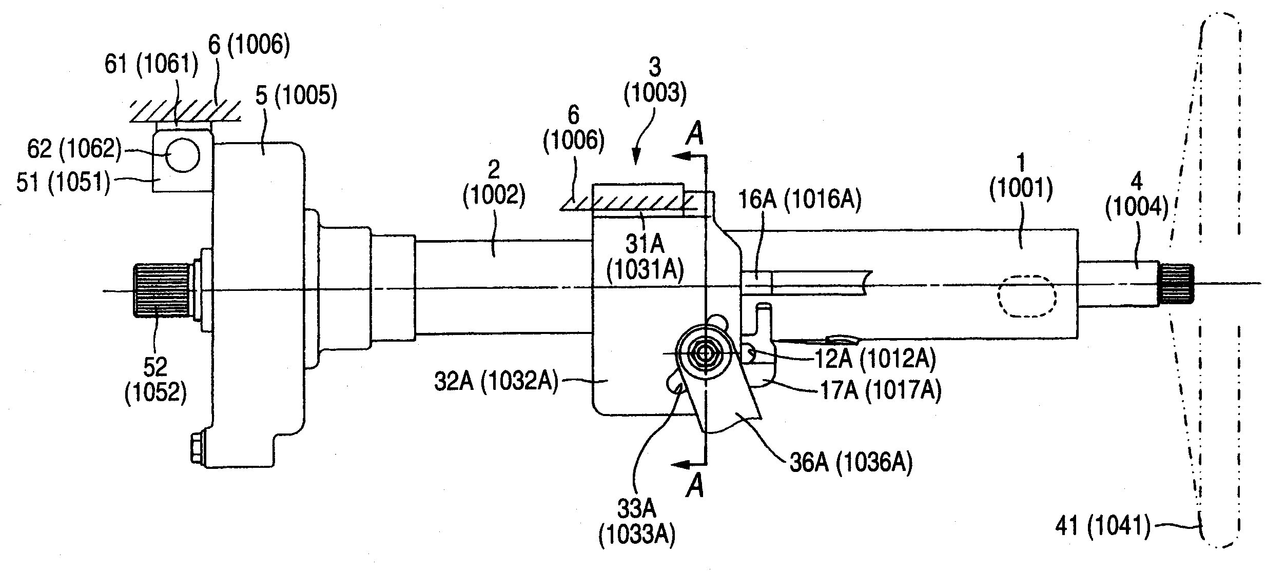
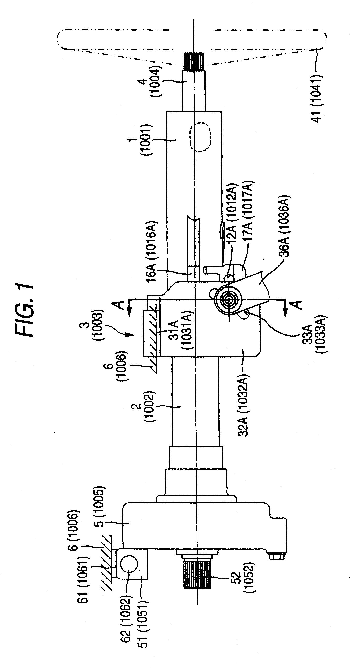
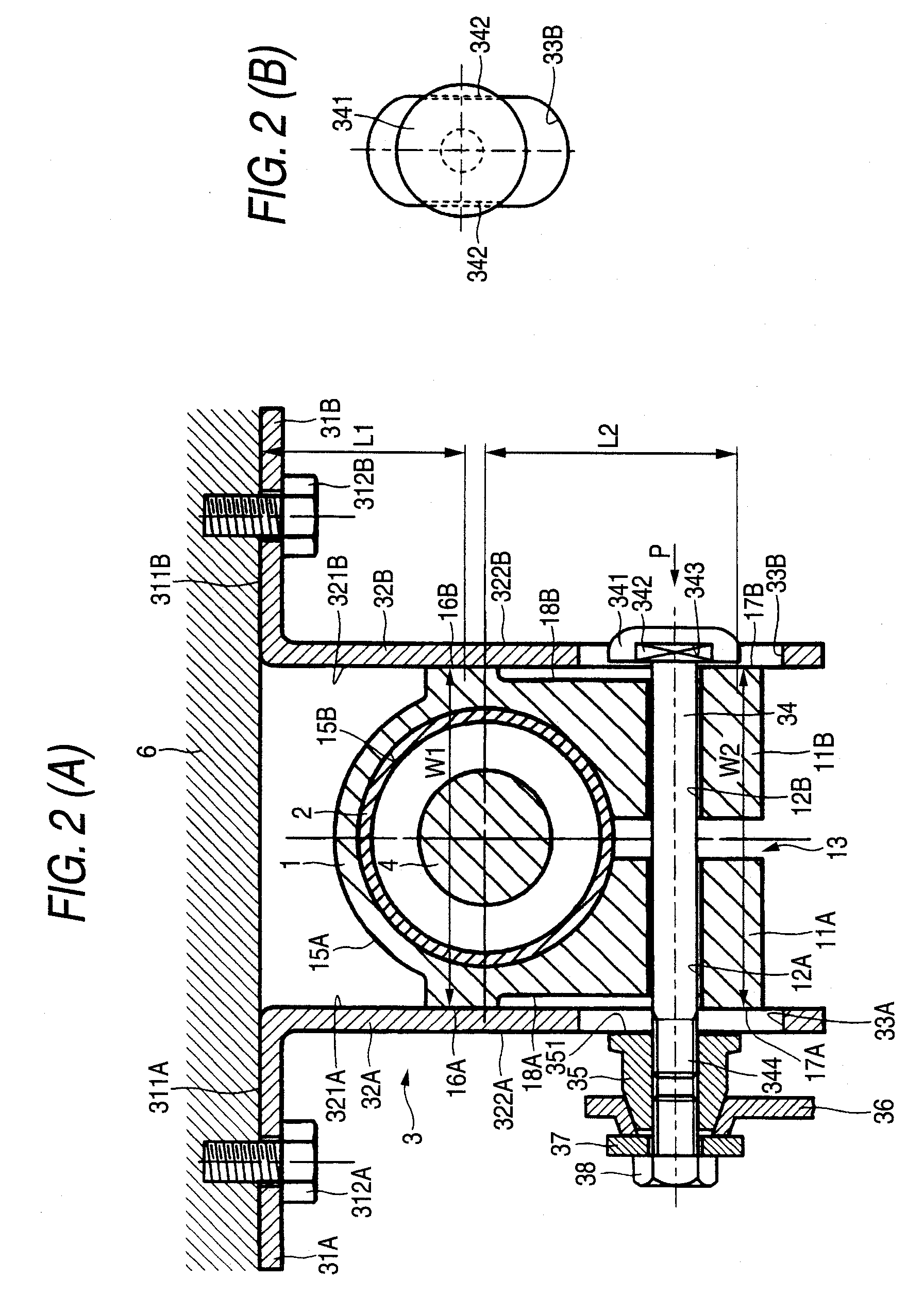
[0172]FIG. 1 is an entire front view showing a steering device of a first embodiment of the present invention, FIG. 2(A) is an enlarged sectional view taken along a line A-A of FIG. 1. FIG. 2(B) is a view seen from an arrow P of FIG. 2(A). FIG. 3 is a diagram of parts showing a simple substance of an outer column shown in FIG. 1.

[0173]In a hollow cylindrical outer column 1, a steering shaft 4 to which a steering wheel 41 is attached in the rear side of a vehicle body (a right side of FIG. 1) is supported so as to freely rotate. The outer column 1 is integrally formed by a die cast molding method in which molten metal such as aluminum alloy, magnesium alloy or the like is poured into a mold under applying pressure.

[0174]To a cylindrical inner peripheral surface 15B (see FIG. 2 (1)) formed in a part of the outer column 1 in the front side of the vehicle body (a left side of FIG. 1), an inner column 2 is internally fitted so as to axially slide (so that a telescopic position can be adj...

second embodiment

[0196]Now, a second embodiment of the present invention will be described below FIG. 4 is an enlarged sectional view showing a steering device of a second embodiment of the present invention and corresponding to the enlarged sectional view taken along a line A-A of FIG. 1. In a below-described explanation, only structural parts different from those of the first embodiment will be described and a duplicated explanation will be omitted. The same parts as those of the first embodiment are designated by the same reference numerals and described.

[0197]The second embodiment is a modified embodiment of the first embodiment in which a fastening rod 34 is arranged between the axis of an outer column 1 and a vehicle body 6. Namely, as shown in FIG. 4, between the inner surfaces 321A and 321B of side plates 32A and 32B of a vehicle body attaching bracket 3, the side surfaces of the outer column 1 and the side surfaces of clamp parts 11A and 11B integrally formed upward from the outer column 1 ...

third embodiment

[0215]Now, a third embodiment of the present invention will be described below. FIG. 5 is an enlarged sectional view showing a steering device of a third embodiment of the present invention and corresponding to the enlarged sectional view taken along a line A-A of FIG. 1. In a below-described explanation, only structural parts different from those of the above-described embodiments will be described and a duplicated explanation will be omitted. The same parts as those of the above-described embodiments are designated by the same reference numerals and described.

[0216]In the first embodiment, the outer column 1 and the clamp parts 11A and 11B are integrally formed by a die casting method. The second embodiment is an example in which the clamp parts 11A and 11B are formed separately from the outer column 1

[0217]As shown in FIG. 5, an outer column 1 is formed with a cylindrical steel pipe and clamp parts 19 made of a separately formed plate and formed in U-shapes are attached to a lowe...


PUM


Abstract

A steering device including a column rotatably supporting a steering shaft on which a steering wheel is mounted; a vehicle body attaching bracket that is attachable to a vehicle body and has a pair of right and left side plates for holding right and left side surfaces of the column therebetween; a fastening rod spaced from the axis of the column and inserted into the side plates of the vehicle body attaching bracket and the column; and fastening members arranged at both ends of the fastening rod to fasten the inner surfaces of the side plates to the side surfaces of the column, wherein contact surfaces of the right and left side surface of the column and the inner surfaces of the side plates are formed in two parts including a part near the axis of the fastening rod and a part spaced from the axis of the fastening rod.

Description

TECHNICAL FIELD[0001]The present invention relates to a steering device and more particularly to a steering device in which the telescopic position (a forward and backward position) or the tilting position (an inclination angle) of a steering wheel is adjustable in accordance with a physique or a driving position of a driver.BACKGROUND ART[0002]In the steering device that the telescopic position or the tilting position of the steering wheel is adjustable, after the telescopic position or the tilting position of the steering wheel is adjusted, a column is firmly clamped to a vehicle body attaching bracket so that the steering wheel does not move from that position.[0003]As a steering device in which a telescopic position is adjustable and an outer column is clamped to an inner column, there is a steering device disclosed in Patent Document 1. In the steering device disclosed in the Patent Document 1, since the inner column is strongly fastened to the outer column, a position offsetti...

Claims


Application Information

Patent Timeline
Patent Type & Authority Applications(United States)
IPC IPC(8): B62D1/18
CPCB62D1/184
Inventor MORIYAMA, SEIICHIFUJIKAWA, KENJI
Owner NSK LTD
Why Eureka
Try Eureka