Housing with glass window for optical instruments in high pressure underwater environments

a technology of optical instruments and glass windows, applied in the field of optical systems, can solve problems such as distorted images coming through glass ports, insufficient wide lens built-in to digital cameras, and certain issues such as the effect of affecting the quality of optical instruments

Active Publication Date: 2008-10-16
RAYTHEON CANADA LTD
View PDF11 Cites 18 Cited by
  • Summary
  • Abstract
  • Description
  • Claims
  • Application Information

AI Technical Summary

Benefits of technology

[0012]The need in the art is addressed by the system and method of the present invention. Generally, the inventive system includes a housing for underwater imaging comprising a first section for retaining an optical instrument; a second section secured to the first section adapted to house a window; a window disposed within the second section; and a buffer ring disposed between the window and the first section. The buffer ring is a material having a coefficient of thermal expansion approximately equal to that of the window.
[0013]In the best mode, the window is optical grade

Problems solved by technology

Unfortunately, as is known in the art, certain issues arise when using cameras inside a watertight housing.
First, because of refraction, the image coming through the glass port will be distorted, in particular when using wide-angle lenses.
Secondly, some digital cameras do not have sufficiently wide lenses built into

Method used


Image

  • Housing with glass window for optical instruments in high pressure underwater environments
  • Housing with glass window for optical instruments in high pressure underwater environments
  • Housing with glass window for optical instruments in high pressure underwater environments

Examples


Embodiment Construction

[0019]Illustrative embodiments and exemplary applications will now be described with reference to the accompanying drawings to disclose the advantageous teachings of the present invention.

[0020]While the present invention is described herein with reference to illustrative embodiments for particular applications, it should be understood that the invention is not limited thereto. Those having ordinary skill in the art and access to the teachings provided herein will recognize additional modifications, applications, and embodiments within the scope thereof and additional fields in which the present invention would be of significant utility.

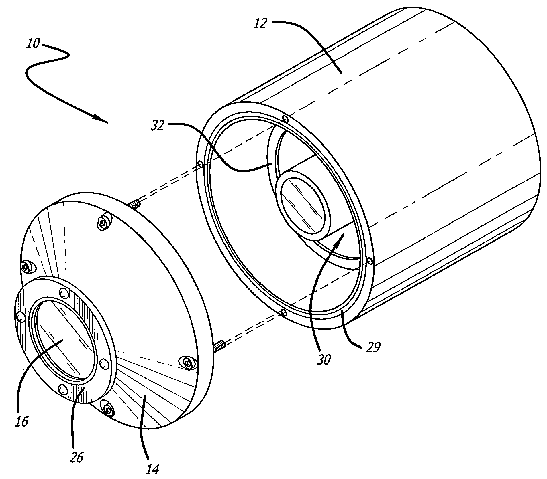
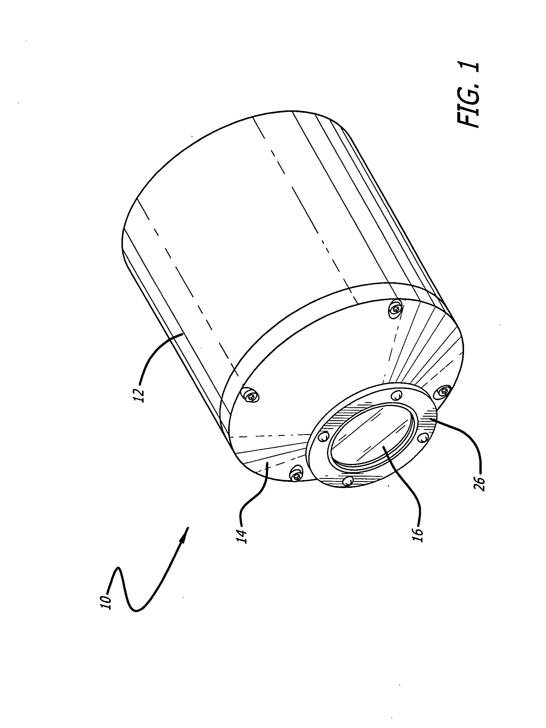
[0021]FIG. 1 is a front left perspective view of a camera housing for deep-sea exploration implemented in accordance with an illustrative embodiment of the present teachings. The inventive housing 10 is shown in a closed position and has a first section 12 for housing an optical instrument; a second section 14 secured to the first section adapted to ...


PUM


Abstract

A housing for underwater imaging comprising a first section for housing an optical instrument; a second section secured to the first section adapted to house a window; a window disposed within the second section; and a buffer ring disposed between the window and the first section. The buffer ring is a material having a coefficient of thermal expansion approximately equal to that of the window. In the best mode, the window is optical grade glass and the buffer ring is aluminum foil. In the illustrative embodiment, a mounting ring is disposed between the buffer ring and the second section of the housing. The mounting ring is steel and must be polished, lapped, stainless steel as well. The buffer ring protects the glass window from the mounting ring. A third ring is disposed over the window and secures it to the second section of the housing. The second section is removable relative to the first section to allow for a camera to be placed within the housing and secured thereby for deep-sea underwater use at high pressure.

Description

BACKGROUND OF THE INVENTION[0001]1. Field of the Invention[0002]The present invention relates to optical and mechanical devices and systems. More specifically, the present invention relates to optical systems used for deep-sea underwater exploration.[0003]2. Description of the Related Art[0004]A variety of cameras are often used to record imagery during deep-sea underwater exploration. Underwater photographers have two basic options for equipment. The first is using an amphibious or waterproof camera such as the Nikonos, which is designed specifically for use underwater. More often, underwater imaging is achieved by putting a traditional film or digital camera into an watertight underwater housing. This allows many more options, since the user can choose a housing specific to their everyday “land” camera, as well as utilize any lens in their collection. For more on this topic, see Wikipedia, the free encyclopedia at http: / / en.wikipedia.org / wiki / Underwater_photogaphy#Camera_Equipment...

Claims


Application Information

Patent Timeline
IPC IPC(8): G03B17/08
CPCG03B17/08
Inventor GOUROVA, SVETLANA
Owner RAYTHEON CANADA LTD
Why Eureka
Try Eureka