
Swash Plate Anti-Torque Mechanism

Inactive Publication Date: 2008-10-16
SIKORSKY AIRCRAFT CORP
View PDF9 Cites 42 Cited by
  • Summary
  • Abstract
  • Description
  • Claims
  • Application Information

AI Technical Summary

Benefits of technology

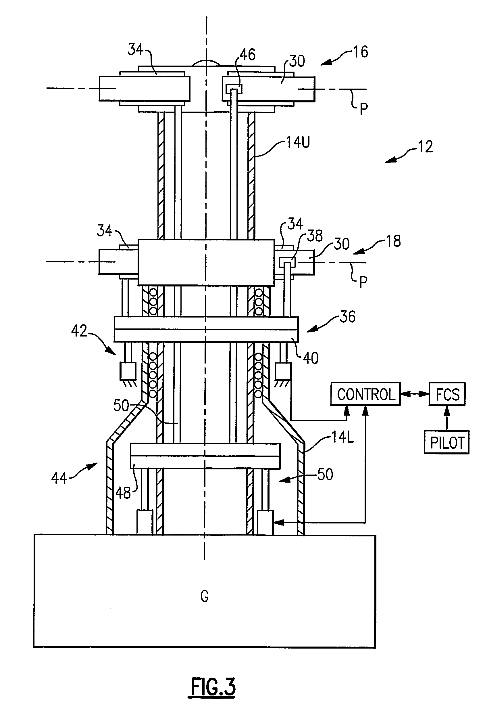
[0015]The anti-torque mechanism requires only the single spherical bearing and further reduces part count by replacing two links and two bolts of a conventional scissors arrangement with a single rigid anti-torque shaft. The anti-torque mechanism facilitates optimal placement of the compound bearing in-line with the swashplate force which is reacted through the rigid anti-torque shaft rather than through a couple at the journal-thrust bearing of a conventional scissor assembly arrangement. Moreover, where space between the swashplate and the hub is relatively limited, the anti-torque mechanism places the swashplate attachment point a relatively significant distance from the rotor axis of rotation to reduce tangential loads on the compound bearing.
[0018]The present invention therefore provides an uncomplicated, light weight, anti-torque mechanism for a swashplate assembly having degrees of freedom in axial, radial and pivot directions so as to replace one or both of the stationary and / or rotating scissor assembly.

Problems solved by technology

Moreover, where space between the swashplate and the hub is relatively limited, the anti-torque mechanism places the swashplate attachment point a relatively significant distance from the rotor axis of rotation to reduce tangential loads on the compound bearing.

Method used


Image

  • Swash Plate Anti-Torque Mechanism
  • Swash Plate Anti-Torque Mechanism
  • Swash Plate Anti-Torque Mechanism

Examples


Embodiment Construction

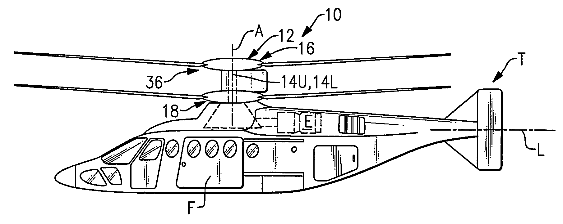
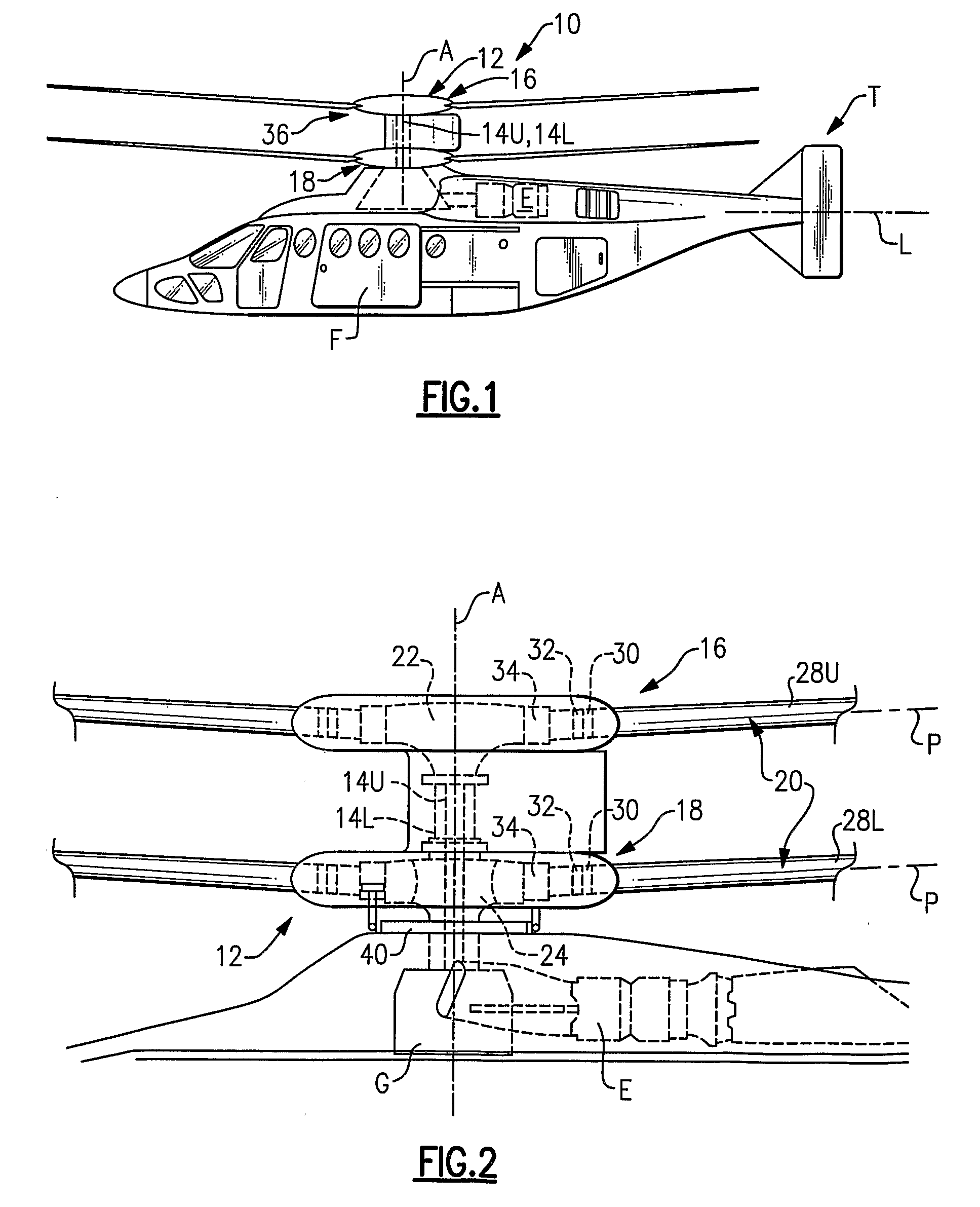
[0035]FIG. 1 illustrates an exemplary vertical takeoff and landing (VTOL) rotary-wing aircraft 10 having a dual, counter-rotating, coaxial rotor system 12 which rotates through a counter-rotating main rotor shaft 14U, 14L (FIG. 2) about an axis of rotation A. The aircraft 10 includes an airframe F which supports the dual, counter rotating, coaxial rotor system 12 as well as an optional translational thrust system T which provides translational thrust during high speed forward flight generally parallel to an aircraft longitudinal axis L. Although a particular counter-rotating, coaxial rotor system aircraft configuration is illustrated in the disclosed embodiment, other rotor systems and other aircraft types such as tilt-wing and tilt-rotor aircraft will also benefit from the present invention.

[0036]A main gearbox G is driven by one or more engines (illustrated schematically at E) drives the rotor system 12. The translational thrust system T may also be driven by the same main gearbox...


PUM


Abstract

An anti-torque mechanism which permits a full range of swashplate assembly motion. The anti-torque mechanism generally includes an anti-torque shaft and a compound bearing mounted thereto to provide five-degrees-of-freedom (spherical-linear-elastomeric) so as to permit a swashplate attachment point to move axially in response to pitch input; pivot in response to swashplate tilt; and move in / out in the radial direction.

Description

[0001]The present application claims priority to U.S. Provisional Patent Application Ser. No. 60 / 724,036, filed Oct. 5, 2005.[0002]This invention was made with government support under U.S. Navy Contract No. N00019-03-G-0003, Delivery Order 0025. The government therefore has certain rights in this invention.BACKGROUND OF THE INVENTION[0003]The present invention relates to a rotary-wing aircraft swashplate assembly, and more particularly to a swashplate assembly with a compound bearing having degrees of freedom in axial, radial and pivot directions so as to replace one or both of the stationary and / or rotating scissors.[0004]Control of a rotary-wing aircraft is affected through cyclic and collective pitch control. Blade pitch control of a rotary-wing aircraft main rotor system is typically achieved through a swashplate assembly which transfers the motion of non-rotating servo-driven control members within a stationary field to the rotating members within a rotational field.[0005]The ...

Claims


Application Information

Patent Timeline
Patent Type & Authority Applications(United States)
IPC IPC(8): B64C27/54
CPCB64C27/10B64C27/605
Inventor CABRERA, PEDRO L.POULIN, STEPHEN V.FEDERICI, FRANCIS D.
Owner SIKORSKY AIRCRAFT CORP
Learn More