Anterior cervical plates for spinal surgery employing anchor backout prevention devices, and related systems and methods
a technology of anterior cervical plate and backout prevention, which is applied in the field of osteosynthesis system and related assemblies and methods, can solve the problems of inability of the attending surgeon to accurately position the anterior cervical plate, prolong the surgery to the detriment of the patient, and unreliable performance, so as to reduce the relative motion between vertebrae, prolong the useful life of the anterior cervical plate within the patient, and reduce the risk of failure
- Summary
- Abstract
- Description
- Claims
- Application Information
AI Technical Summary
Benefits of technology
Problems solved by technology
Method used
Image
Examples
second embodiment
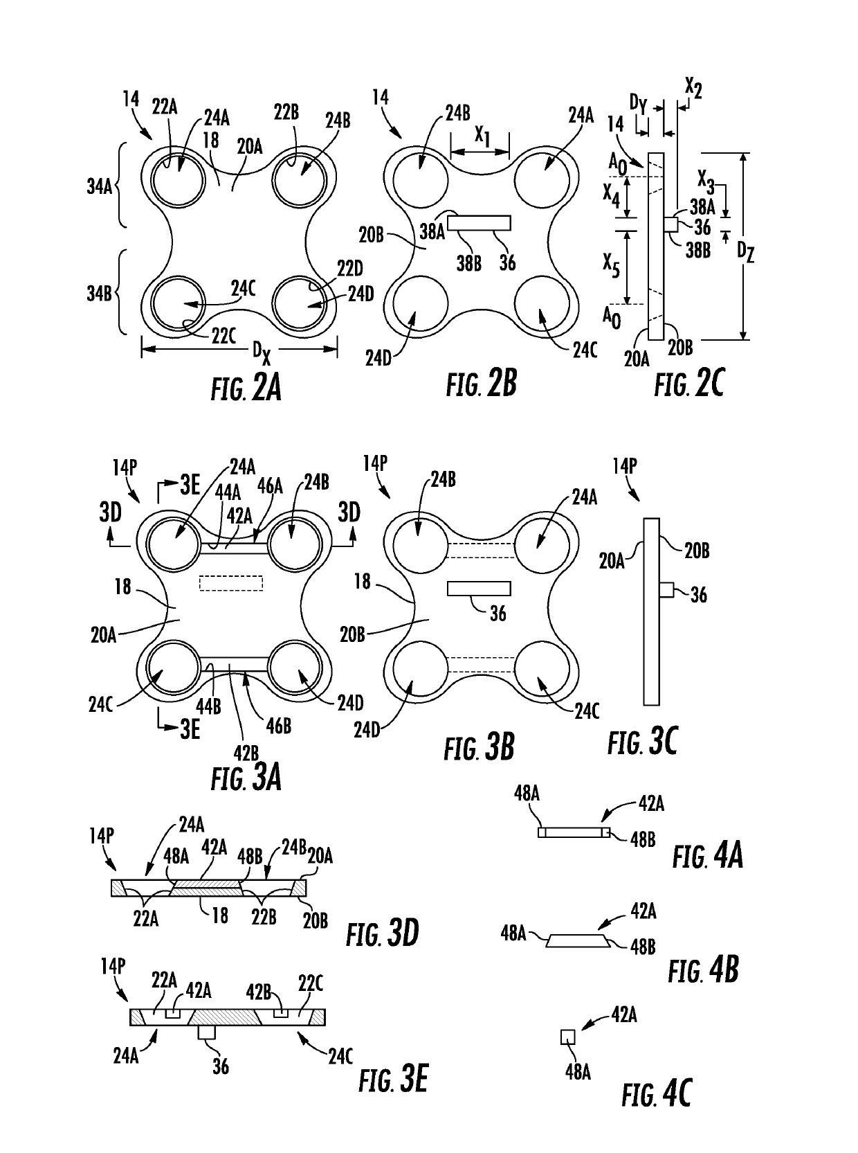
[0017]FIGS. 3A through 3E are a front view, a rear view, a right side view, a bottom sectional view, and a left sectional view, respectively, of an exemplary second anterior cervical plate which is the anterior cervical plate of FIG. 2A, including at least one exemplary locking magnet fixed to the main body of the second anterior cervical plate;
[0018]FIGS. 4A through 4C are a top view, a front view, and a left side view of the at least one locking magnet of FIG. 3A;
[0019]FIGS. 5A and 5B are bottom sectional views of exemplary bone anchors coupled to the second anterior cervical plate of FIG. 3A, wherein outer surfaces of heads of the bone anchors includes linear and curved profiles, respectively;
[0020]FIG. 5C is a right side view of the anterior cervical plate of FIG. 3A fusing the first and second vertebrae together, wherein the at least one locking magnet creates a magnetic field;
[0021]FIG. 5D is a right side view of the anterior cervical plate system of FIG. 3A fusing the first a...
third embodiment
[0023]FIGS. 6A-1 and 6A-2 are a front view and a bottom sectional view, respectively, of an exemplary third anterior cervical plate which is the anterior cervical plate of FIG. 2A, including at least one exemplary locking magnet movable relative to a main body of the third anterior cervical plate, wherein the locking magnets are illustrated in open positions;
[0024]FIGS. 6B-1 and 6B-2 are a front view and a bottom sectional view, respectively, of the third anterior cervical plate of FIG. 6A-1, wherein the locking magnets are illustrated in closed positions;
[0025]FIGS. 7A through 7C are a front view, a bottom view, and a left side view, respectively, of one of the locking magnets of FIG. 6A-1;
fourth embodiment
[0026]FIGS. 8A and 8B are a front view and a bottom sectional view, respectively, of an exemplary fourth anterior cervical plate which is the anterior cervical plate of FIG. 2A, including at least one exemplary locking magnet movable relative to the main body of the fourth anterior cervical plate and at least one secondary magnet, wherein the locking magnets are illustrated in open positions;
[0027]FIG. 8C is a bottom sectional view of the fourth anterior cervical plate of FIG. 8B engaged with a bone anchor, wherein the locking magnet is shown in a closed position coupled to a head of the bone anchor;
PUM
 Abstract
Description
Claims
Application Information
 - R&D
- Intellectual Property
- Life Sciences
- Materials
- Tech Scout
- Unparalleled Data Quality
- Higher Quality Content
- 60% Fewer Hallucinations
Browse by: Latest US Patents, China's latest patents, Technical Efficacy Thesaurus, Application Domain, Technology Topic, Popular Technical Reports.
© 2025 PatSnap. All rights reserved.Legal|Privacy policy|Modern Slavery Act Transparency Statement|Sitemap|About US| Contact US: help@patsnap.com


