Anterior Cervical Plates For Spinal Surgery Employing Anchor Blackout Prevention Devices, And Related Systems And Methods

a technology of blackout prevention device and anterior cervical plate, which is applied in the field of osteosynthesis system and related assemblies and methods, can solve the problems of inability to accurately position the anterior cervical plate, prolong the surgery to the detriment of the patient, and unreliable performance, so as to reduce the relative motion between vertebrae, prolong the useful life of the anterior cervical plate within the patient, and reduce the risk of failure

Active Publication Date: 2017-01-12
DESIGN ENTERPRISES LLC
View PDF6 Cites 5 Cited by
  • Summary
  • Abstract
  • Description
  • Claims
  • Application Information

AI Technical Summary

Benefits of technology

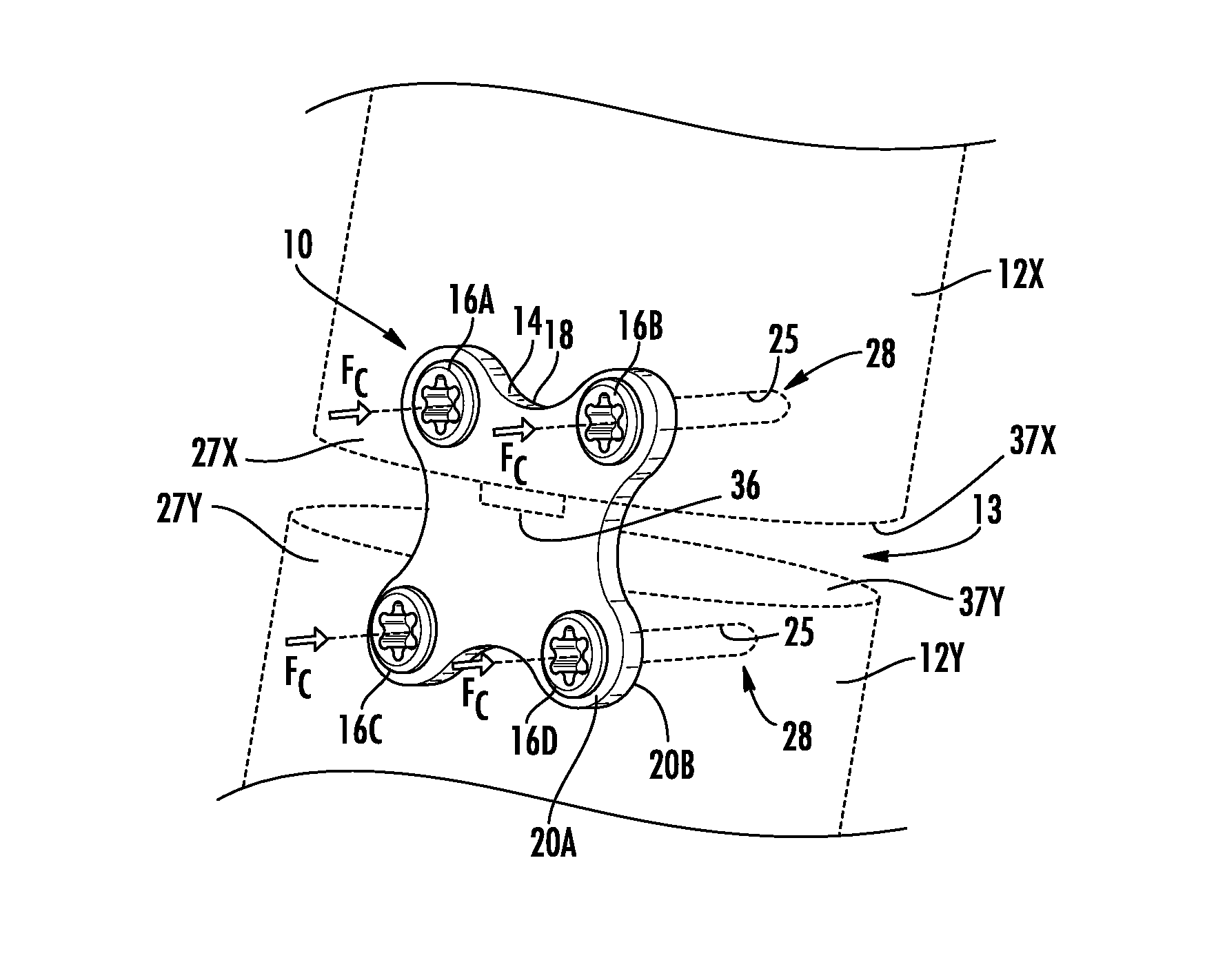
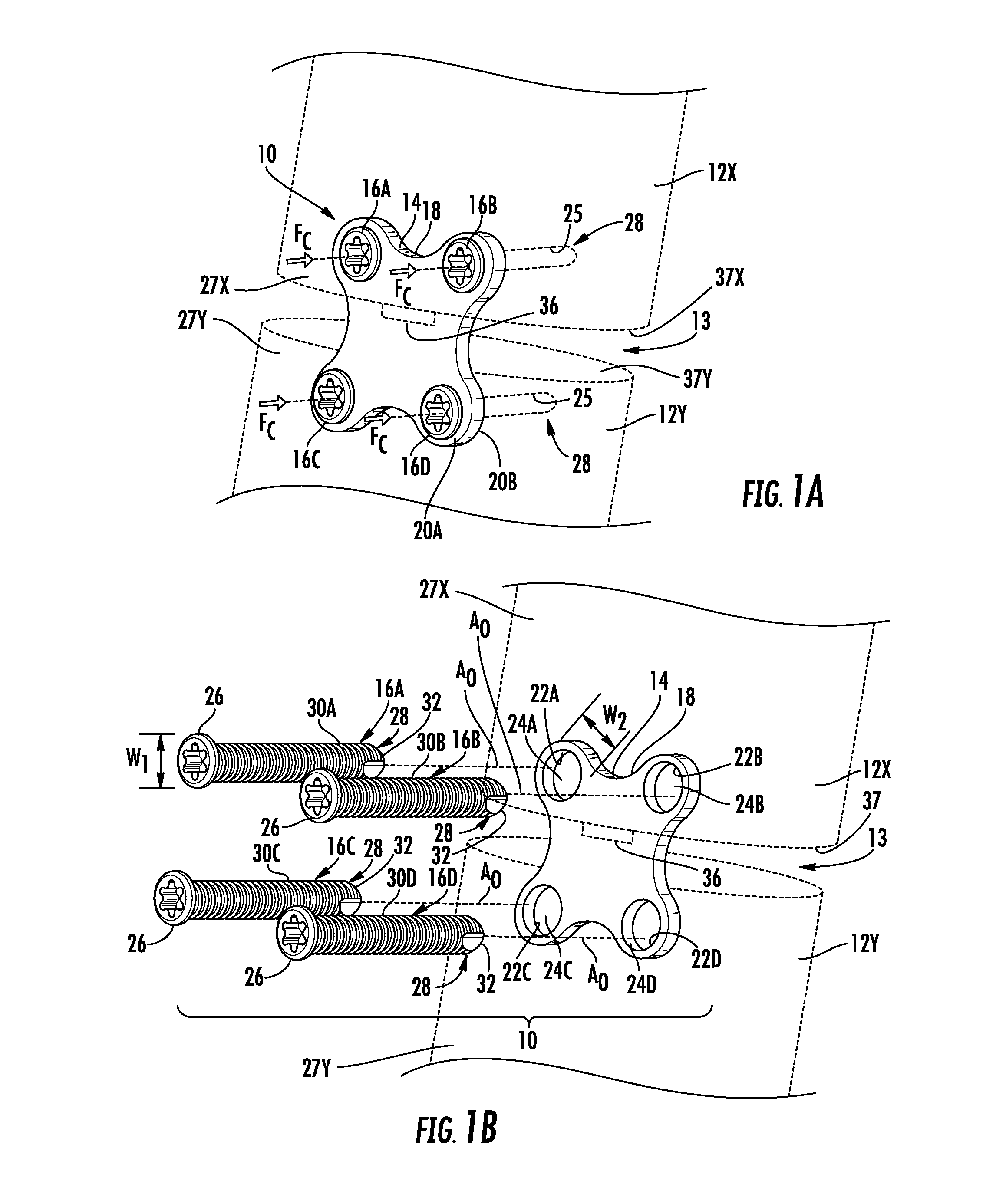
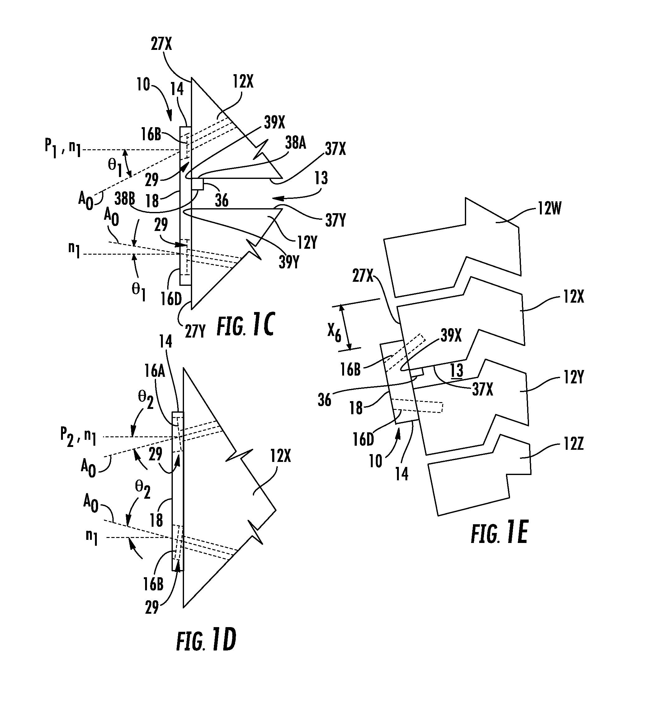
[0007]Embodiments disclosed herein include anterior cervical plates for spinal surgery employing anchor backout prevention devices, and related systems and methods. A spinal column includes vertebrae in an articulating structure. Medical intervention may involve limiting the relative motion between vertebrae by fusing at least first and second vertebrae together with osteosynthesis systems. The systems include a plate attached to anterior surfaces of the first and second vertebrae with ancho

Problems solved by technology

One drawback of conventional anterior cervical plates is that it can be difficult for an attending surgeon to accurately position the anterior cervical plate prior to affixing the anterior cervical plate with the bone anchors and/or maintain the plate in a desired position during the imp

Method used


Image

  • Anterior Cervical Plates For Spinal Surgery Employing Anchor Blackout Prevention Devices, And Related Systems And Methods
  • Anterior Cervical Plates For Spinal Surgery Employing Anchor Blackout Prevention Devices, And Related Systems And Methods
  • Anterior Cervical Plates For Spinal Surgery Employing Anchor Blackout Prevention Devices, And Related Systems And Methods

Examples


second embodiment

[0019]FIGS. 3A through 3E are a front view, a rear view, a right side view, a bottom sectional view, and a left sectional view, respectively, of an exemplary second anterior cervical plate which is the anterior cervical plate of FIG. 2A, including at least one exemplary locking magnet fixed to the main body of the second anterior cervical plate;

[0020]FIGS. 4A through 4C are a top view, a front view, and a left side view of the at least one locking magnet of FIG. 3A;

[0021]FIGS. 5A and 5B are bottom sectional views of exemplary bone anchors coupled to the second anterior cervical plate of FIG. 3A, wherein outer surfaces of heads of the bone anchors includes linear and curved profiles, respectively;

[0022]FIG. 5C is a right side view of the anterior cervical plate of FIG. 3A fusing the first and second vertebrae together, wherein the at least one locking magnet creates a magnetic field;

[0023]FIG. 5D is a right side view of the anterior cervical plate system of FIG. 3A fusing the first a...

third embodiment

[0025]FIGS. 6A-1 and 6A-2 are a front view and a bottom sectional view, respectively, of an exemplary third anterior cervical plate which is the anterior cervical plate of FIG. 2A, including at least one exemplary locking magnet movable relative to a main body of the third anterior cervical plate, wherein the locking magnets are illustrated in open positions;

[0026]FIGS. 6B-1 and 6B-2 are a front view and a bottom sectional view, respectively, of the third anterior cervical plate of FIG. 6A-1, wherein the locking magnets are illustrated in closed positions;

[0027]FIGS. 7A through 7C are a front view, a bottom view, and a left side view, respectively, of one of the locking magnets of FIG. 6A-1;

fourth embodiment

[0028]FIGS. 8A and 8B are a front view and a bottom sectional view, respectively, of an exemplary fourth anterior cervical plate which is the anterior cervical plate of FIG. 2A, including at least one exemplary locking magnet movable relative to the main body of the fourth anterior cervical plate and at least one secondary magnet, wherein the locking magnets are illustrated in open positions;

[0029]FIG. 8C is a bottom sectional view of the fourth anterior cervical plate of FIG. 8B engaged with a bone anchor, wherein the locking magnet is shown in a closed position coupled to a head of the bone anchor;


PUM


Abstract

Anterior cervical plates for spinal surgery employing anchor backout prevention devices, and related systems and methods are disclosed. A spinal column includes vertebrae in an articulating structure. Medical intervention may involve limiting the relative motion between vertebrae by fusing at least first and second vertebrae together with osteosynthesis systems. The systems include a plate attached to anterior surfaces of the first and second vertebrae with anchors extending through passageways in the plate. By including one or more anchor backout prevention devices to the plate, movements causing the anchors to disengage from the vertebrae may be avoided. The devices may include a positioning guide, and locking magnets. The implementation of a combination of these devices into the plate may provide greater robustness against failure than any of the devices individually. In this manner, the useful life of the plate within a patient may be lengthened.

Description

CROSS-REFERENCE To RELATED APPLICATION[0001]This application claims benefit of U.S. Provisional Patent Ser. No. 62 / 189,937 filed on Jul. 8, 2015 and entitled “Cervical Plate Systems and Method of Use,” which is incorporated herein by reference in its entirety.BACKGROUND[0002]Field of the Disclosure[0003]The technology of the disclosure relates to osteosynthesis systems and related assemblies and methods for connecting bones or portions of bones to each other in an animal, such as a human.[0004]Technical Background[0005]A vertebral column and a spinal cord of a patient extend from the skull to the pelvis and form a longitudinal axis of a patient. The column includes vertebra that are separated by fibrocartilage structures (intervertebral disks) that are interconnected with ligaments. The vertebral column protects the spinal cord and provides structural support for the patient. The spinal cord along with a bundle of nerve fibers extending from the spinal cord form a central nervous sy...

Claims


Application Information

Patent Timeline
IPC IPC(8): A61B17/70
CPCA61B17/7059A61B2017/00876A61B2017/567A61B2017/681A61B17/8052A61B17/808
Inventor GARRIDO, BENITO J.
Owner DESIGN ENTERPRISES LLC
Why Eureka
Try Eureka