Teeth Cleaning Apparatus

a cleaning apparatus and a technology for teeth, applied in saliva removers, medical science, dentistry, etc., can solve the problems of affecting the cleaning effect of teeth, so as to facilitate the extraction of debris, facilitate the application of vacuum, and facilitate the introduction of convenient features

Active Publication Date: 2008-10-16
COATES ERIC LEONARD
View PDF16 Cites 13 Cited by
  • Summary
  • Abstract
  • Description
  • Claims
  • Application Information

AI Technical Summary

Benefits of technology

[0008]Even more preferably, the engagement thread comprises substantially continuous helical thread with a small helix angle with respect to a plane transverse to the axis of the implement. The helix angle is preferably less than 60 degrees or, even more preferably, less than 20 degrees.
[0009]In some embodiments, the apparatus also comprises a pump arranged to provide vacuum, the vacuum being applied in the interproximal space adjacent the cleaning implement to facilitate extraction of debris, the extracted debris being then flushed out of the cleaning apparatus or transferred to a dedicated storage space.
[0010]Preferably, the housing comprises a rear portion, including the driving mechanism, and a front portion, including an elongate tubular support portion for housing and laterally supporting the cleaning implement, the rear and the front portions being axially movable with respect to each other, wherein moving the front portion towards the rear portion effects the operative configuration of the cleaning implement, and moving of the front portion away from the rear portion effects the retracted configuration of the cleaning implement.
[0011]Also preferably, the tubular support portion includes a curved portion to allow the tip of the implement to be conveniently introduced into the interproximal space under an angle with respect to the axis of the cleaning apparatus. The angle of the curved portion is preferably 90 degrees.
[0012]Preferably, the front portion is resiliently biased away from the rear portion, the arrangement being such that, pushing the front portion towards the rear portion effects the operative configuration of the cleaning implement, while releasing of the front portion allows the bias to bring the implement into the retracted configuration.
[0013]Preferably, the shaft of the cleaning implement is hollow so as to facilitate applying of vacuum and extracting interproximal debris through at least one opening in the shaft.

Problems solved by technology

All these tools, however, tend to push at least some of the debris through the small gap at the base of the teeth and down below the gum.
In addition, the use of these tools is somewhat inconvenient and less dextrous users, such as those with Multiple Sclerosis or arthritis, or users with large hands, find such a use difficult.
One of the problems is that the cleaning implement used in these automated systems tends to push debris below the gum.
Another problem relates to the fact that a very fine resilient probe, less than 0.5 mm diameter, is required to access very small crevices.
Such a fine probe easily crumples or collapses when compressed during insertion.
Previous attempts have found it difficult to reconcile these contradicting requirements.

Method used


Image

  • Teeth Cleaning Apparatus
  • Teeth Cleaning Apparatus
  • Teeth Cleaning Apparatus

Examples


Embodiment Construction

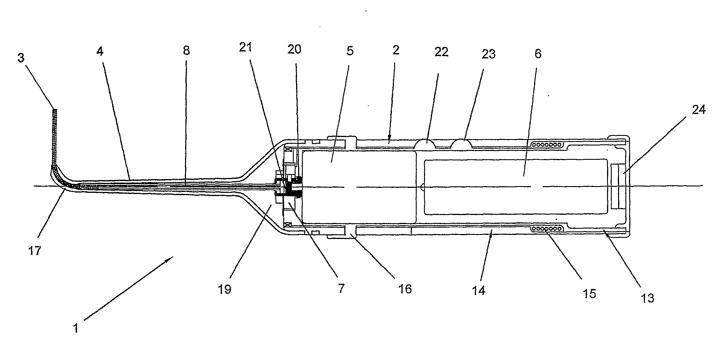
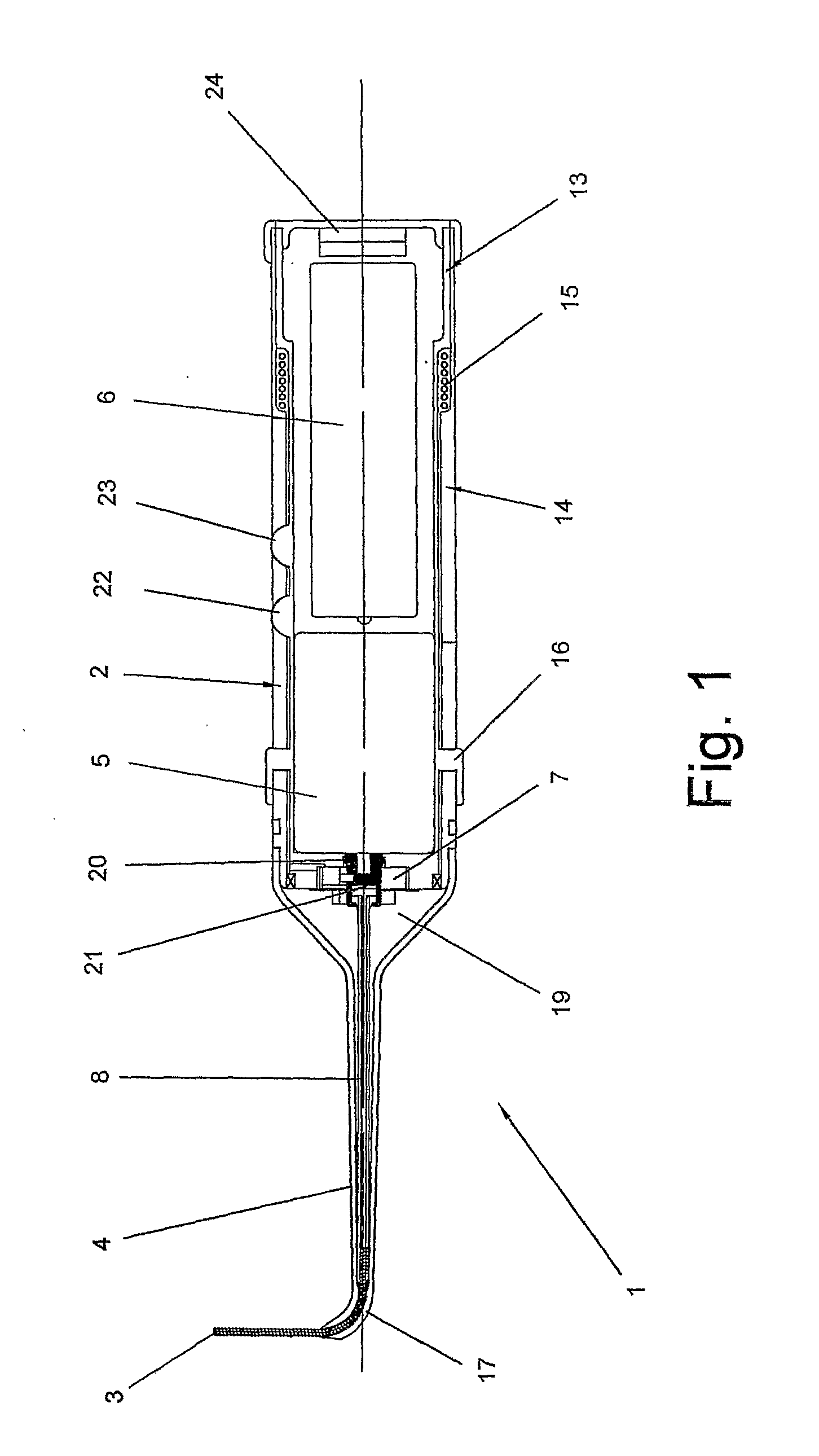
[0032]According to the preferred embodiment of the invention, shown in FIG. 1, there is provided a teeth-cleaning apparatus 1 comprising an elongate housing 2 and a cylindrical cleaning implement 3 that is laterally supported within tubular support portion 4 at the front of the housing. Housing 2 includes the entire driving mechanism of apparatus 1, including electrical motor 5 and battery 6, as well as elements with additional functions, such as pump 7.

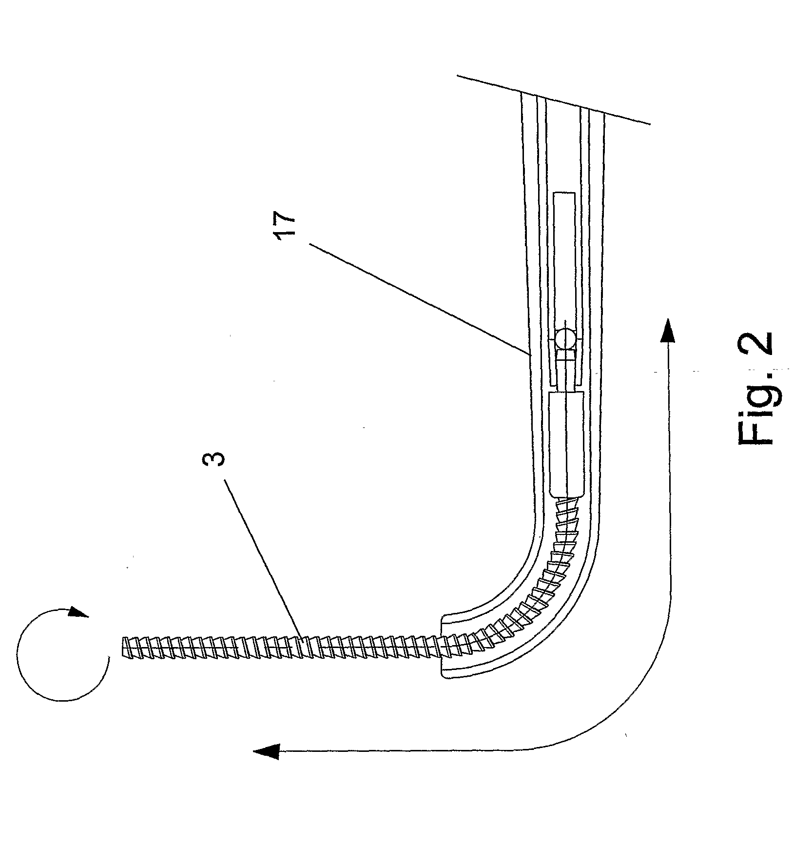
[0033]Electric motor 5 is configured to rotate drive shaft 8 in both directions. Drive shaft 8 then transfers the rotational movement to cleaning implement 3. Clutch 9, schematically shown in FIG. 8, is arranged between motor 5 and drive shaft 8 to facilitate disengagement of drive shaft 8 from motor 5, in case of jamming of implement 3 in the interproximal space. In an alternative embodiment, clutch 9 can be located between drive shaft 8 and cleaning implement 3. Pump 7 is drivingly engaged with an additional shaft, not shown, that ...


PUM


Abstract

Teeth cleaning apparatus comprises a cylindrical cleaning implement. The cleaning implement includes a resilient support shaft and an engagement thread and is drivingly rotatable. The implement is so configured that, when presented between a pair of adjacent teeth, a rotating implement threads itself into the interproximal space and extracts interproximal debris.

Description

TECHNICAL FIELD[0001]The invention described herein relates to an implement and an apparatus for interproximal cleaning and removal of bio-film from user's teeth.BACKGROUND OF THE INVENTION[0002]The conventional tools for Interproximal cleaning and biofilm removal include floss, ribbon and interproximal brushes. All these tools, however, tend to push at least some of the debris through the small gap at the base of the teeth and down below the gum. In addition, the use of these tools is somewhat inconvenient and less dextrous users, such as those with Multiple Sclerosis or arthritis, or users with large hands, find such a use difficult.[0003]There have also been previous attempts to automate the interproximal cleaning. For example, both U.S. Pat. No. 6,102,700, by Haczek et al., and U.S. Pat. No. 6,050,818, by Boland et al., disclose electrical power dental cleaning devices employing a cleaning implement rotated around a longitudinal axis. Various features of the driving mechanisms o...

Claims


Application Information

Patent Timeline
Patent Type & Authority Applications(United States)
IPC IPC(8): A61C17/16
CPCA61C15/00A61C15/047A61C17/043A61C17/08
Inventor COATES, ERIC LEONARD
Owner COATES ERIC LEONARD
Why Eureka
Try Eureka