
Seamless and vertical call handoff solution architecture

a solution architecture and vertical call technology, applied in the field of communication networks, can solve the problems of loss of basic connectivity, poor handoff timing, and main challenge of mobility management, and achieve the effect of facilitating the handoff of communications

Active Publication Date: 2008-10-16
APPLE INC
View PDF6 Cites 61 Cited by
  • Summary
  • Abstract
  • Description
  • Claims
  • Application Information

AI Technical Summary

Benefits of technology

The present invention provides a system and method for smoothly switching a user device from one communication network to another. The system includes an anchor point that connects to both networks and a handoff device that determines when to switch the user device from one network to the other. The anchor point remembers information about previous triggering events and uses it to make informed decisions about when to switch the user device. This invention ensures that users can seamlessly connect to different communication networks and experience no interruptions in their communication.

Problems solved by technology

Mobility management is a main challenge in the converged network.
Presently, the use of poorly configured hysteresis thresholds by the mobile station or MT will typically result in poor handoff timing such as early handoff, late handoff or multiple handoffs.
On the one hand, late handoff decisions by the MT result in loss of basic connectivity, referred to as a “black hole” problem, when there is insufficient time for the completion of handoff operations, e.g., dynamic host configuration protocol (“DHCP”), mobile IP (“MIP”) signaling, network acquisition and authentication, and other control signaling, or there is a lack of coverage overlap between two networks.
On the other hand, early handoff decisions may produce a “ping pong” effect, which is where the MT is unnecessarily switching between the heterogeneous networks, e.g., between WLAN and cellular networks, and is characterized by excessive rates of handoffs, poor quality of service (“QoS”) for real-time flows, and excessive signaling load on network servers.

Method used


Image

  • Seamless and vertical call handoff solution architecture
  • Seamless and vertical call handoff solution architecture
  • Seamless and vertical call handoff solution architecture

Examples


Embodiment Construction

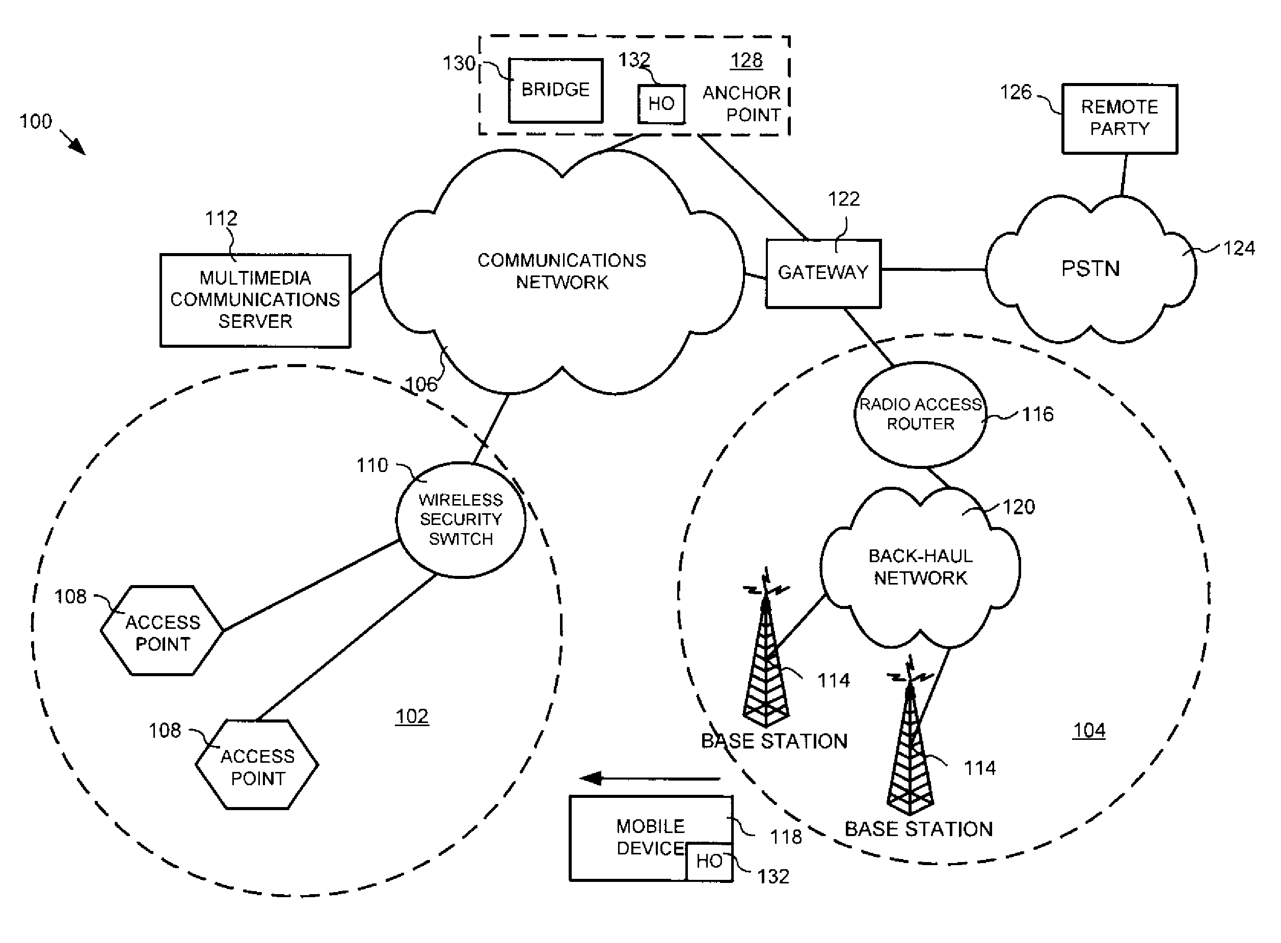
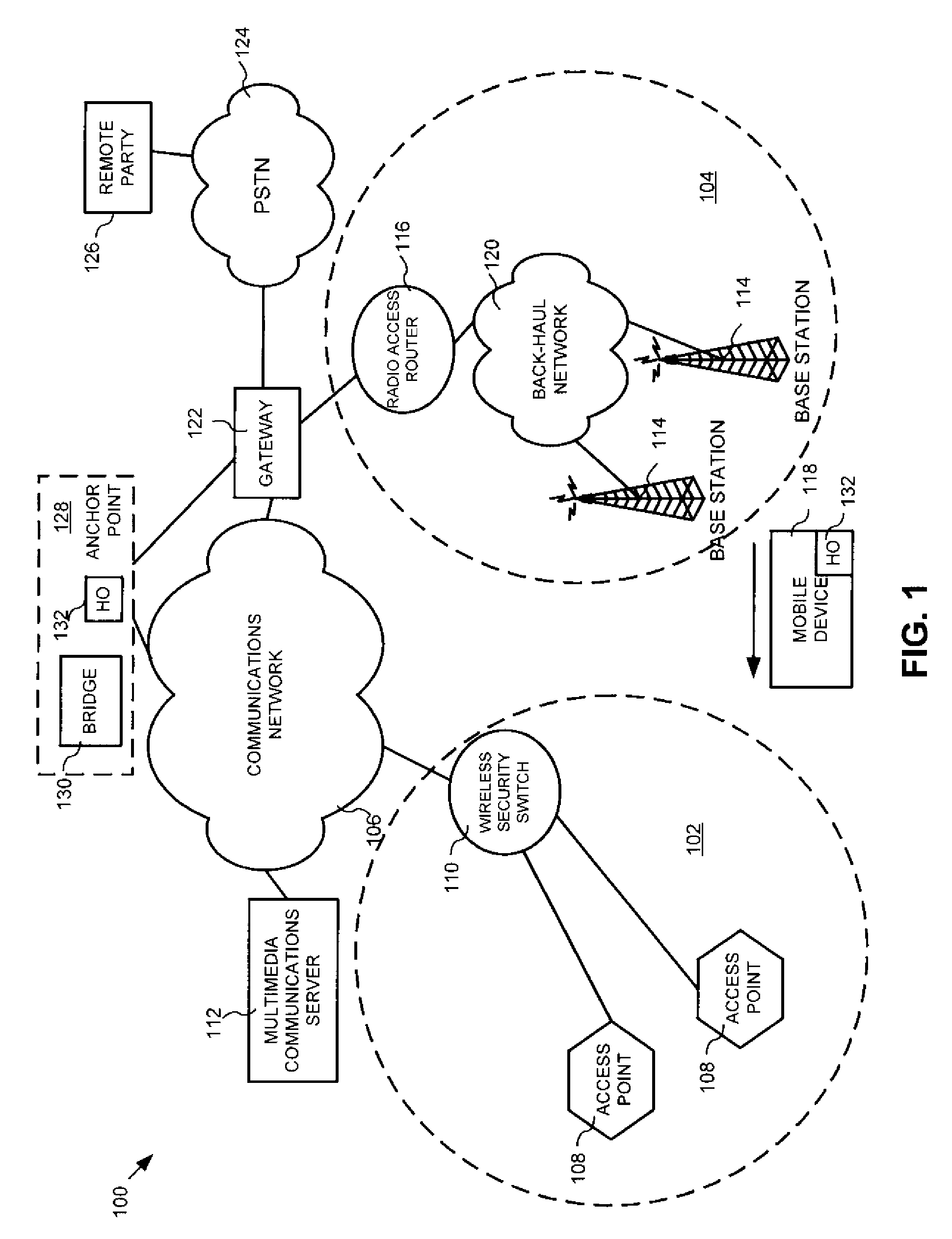
[0020]Referring now to the drawing figures in which like reference designators refer to like elements, there is shown in FIG. 1, a block diagram of the network architecture of an interworking heterogeneous wireless access system constructed in accordance with the principles of the present invention and designated generally as “100”. The system 100 includes a first network 102 having a first domain technology, e.g., a WiFi network, a second network 104 having a second domain technology, e.g., a cellular network, and a communications network 106. It should be noted that although the invention is described with reference to the WiFi protocol and “access points”, the invention may easily be adapted by one of skill in the art to provide identification information to ease the transition between any two networks, including WiFi, WiMAX and others known in the art or later developed. The WiFi network 102 includes access point (“AP”) nodes 108 which are two-way transceivers that broadcast dat...


PUM


Abstract

A system, method and apparatus for facilitating handoff of communications with a user device between a first communication network having a first domain technology, and a second communication network having a second domain technology different from the first domain technology, the system, method and apparatus includes an anchor point that establishes a first service flow with the first communication network, and a second service flow with the second communication network based upon a triggering event respectively, with the user device, and a handoff device that receives at least one handoff parameter for determining a handoff operation of the user device from the first communication network to the second communication network.

Description

CROSS-REFERENCE TO RELATED APPLICATION[0001]This application is related to and claims priority to U.S. Provisional Application Ser. No. 60 / 911,146, filed Apr. 11, 2007, entitled SEAMLESS CALL HANDOFF STATE MACHINE, the entirety of which is incorporated herein by reference.STATEMENT REGARDING FEDERALLY SPONSORED RESEARCH OR DEVELOPMENT[0002]n / aFIELD OF THE INVENTION[0003]The present invention relates to communication networks, and more particularly to a method, system and apparatus that provides for control of call session handoffs across heterogeneous communication networksBACKGROUND OF THE INVENTION[0004]Wireless technologies are evolving toward broadband information access across multiple networking platforms as part of the demand for continuous availability of multimedia applications. Recent trends indicate that wide-area cellular networks based on second, third and fourth generation (“2G”, “3G” and “4G”) standards and wireless local area networks (“WLANs”) will co-exist to offer...

Claims


Application Information

Patent Timeline
Patent Type & Authority Applications(United States)
IPC IPC(8): H04Q7/20H04W36/14H04W36/28
CPCH04W36/0083H04W36/14H04W36/28H04W36/00837H04W36/1446
Inventor ACHTARI, GUYVESBERNIER, ERICFELSKE, KENT
Owner APPLE INC
Learn More