Retractable Syringe with Plunger Disabling System

a technology of syringe and plunger, which is applied in the field of permanent retractable, single-use syringe, can solve the problems of high cost to society of supporting and providing medical attention, unclean needles and syringes, and inadvertent needle-stick injuries, so as to facilitate decompression and reduce the potential for re-use, prevent, minimize or reduce the potential for syringe refilling

Active Publication Date: 2008-10-16
UN HOLDINGS LLC
View PDF40 Cites 50 Cited by
  • Summary
  • Abstract
  • Description
  • Claims
  • Application Information

AI Technical Summary

Benefits of technology

[0031](b) a second plunger member comprising a seal; wherein the first plunger member and the second plunger member are releasably coupled to co-operatively maintain said spring in an initial compressed state and can subsequently be rotatably uncoupled to facilitate decompression of said spring to force retraction of said first plunger member and said needle mount when engaged therewith following depression of said plunger to deliver fluid contents of said syringe and wherein said two pawls are engageable with respective steps on said first plunger member to co-operably prevent subsequent depres...

Problems solved by technology

The practice of sharing syringes without adequate sterilisation between successive users is a major contributor to the transfer of Human Immunodeficiency Virus and Hepatitis with subsequent severe repercussions for the sufferer of such diseases and at a high cost to society of supporting and providing medical attention to those sufferers.
Another significant risk associated with unclean needles and syringes arises from the possibility of inadvertent needle-stick injuries.
This is particularly a problem for law enfo...

Method used


Image

  • Retractable Syringe with Plunger Disabling System
  • Retractable Syringe with Plunger Disabling System
  • Retractable Syringe with Plunger Disabling System

Examples


Embodiment Construction

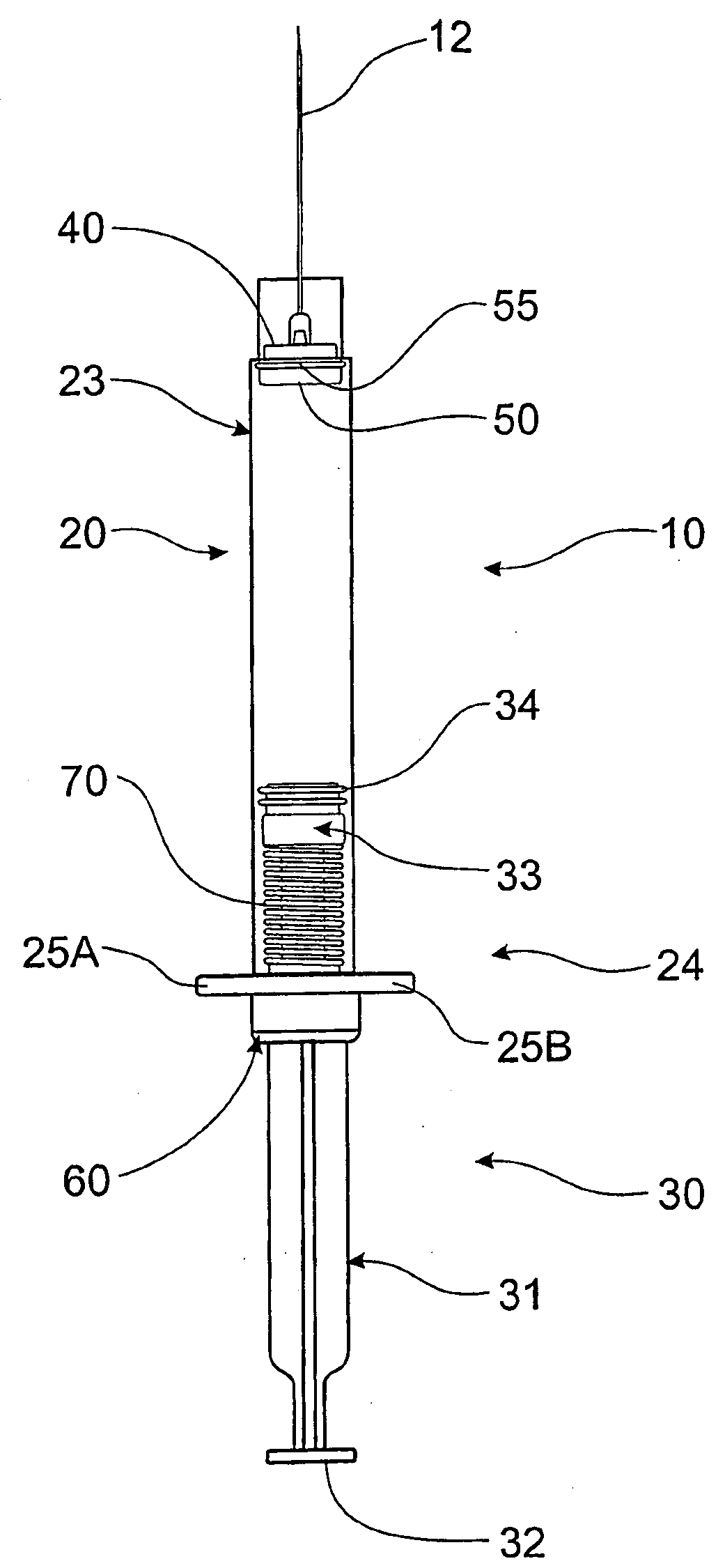
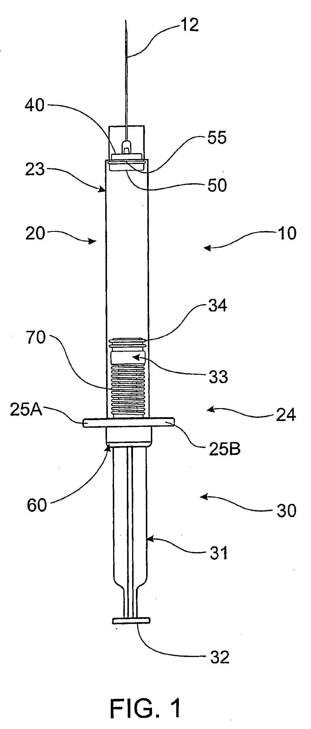
[0047]Referring to an embodiment shown in FIG. 1, retractable syringe 10 comprises barrel 20, plunger 30 operably located therein and needle mount 40 with retractable needle 12. Needle mount 40 is mounted at needle end 23 of barrel 20 with barrel insert 50 and O-ring 55. Finger grips 25A, 25B are provided at plunger end 24 of barrel 20, at which end is mounted collar 60. Plunger 30 comprises first plunger member 31 with button 32 operable by a user and second plunger member 33 and seal 34 mounted thereto, releasably coupled to first plunger member 31 to co-operatively maintain spring 70 in a compressed state until required for retraction of needle mount 40 and needle 12.

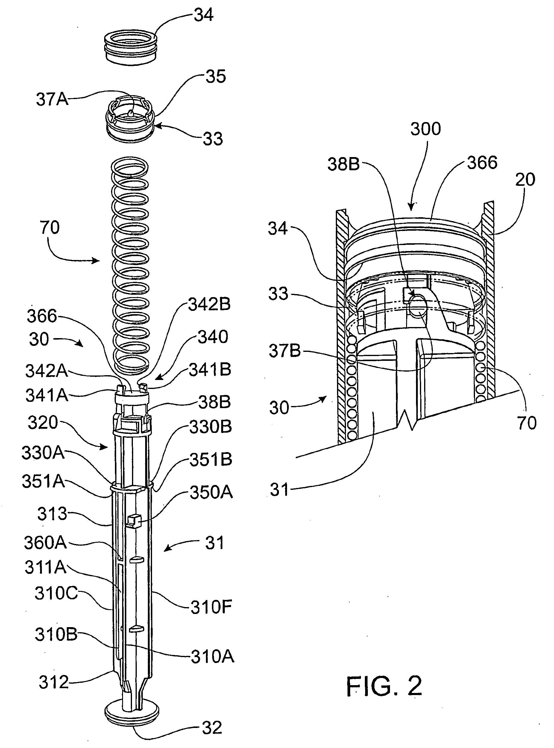
[0048]Referring now to FIG. 2, plunger 30 comprises a first plunger member in the form of plunger rod 31 having button 32 operable by a user, and a second plunger member in the form of seal mount 33. When assembled, seal 34 is mounted to seat 35 in seal mount 33, which seal 34 in use, prevents or minimizes leakage of...


PUM


Abstract

A retractable, single use syringe (10) comprises a barrel (20), a collar (60) mounted to the barrel, a retraction spring (70), a needle mount (40) located at a needle end (23) of the barrel and a plunger (30). The plunger comprises a first plunger member (31) and a second plunger member (33) that are releasably coupled to co-operatively maintain the retraction spring in an initial compressed state. The second plunger member (33) further comprises a seal (34) to prevent fluid leakage between plunger (30) and barrel (20). After depression of the plunger to deliver the fluid contents of the syringe, the first plunger member (31) engages the needle mount (40) with needle (12) attached thereto and is rotatably uncoupled from the second plunger member (33) to allow decompression of the retraction spring (70), which forces retraction of the first plunger member (31), needle mount (40) and needle (12) engaged therewith. The first plunger member (31) and the collar (60) comprise elements that co-operatively form a disabling means that prevents or at least minimizes the likelihood of subsequent depression or withdrawal of the plunger (30). Also following retraction of the first plunger member (31), the second plunger member (33) and seal (34) remains at the needle end (23) of the barrel (20) thereby preventing refilling and re-use of the syringe.

Description

FIELD OF THE INVENTION[0001]This invention relates to a syringe and plunger therefor. More particularly, this invention relates to a permanently retractable, single use syringe where the plunger can be automatically disabled.BACKGROUND OF THE INVENTION[0002]The practice of sharing syringes without adequate sterilisation between successive users is a major contributor to the transfer of Human Immunodeficiency Virus and Hepatitis with subsequent severe repercussions for the sufferer of such diseases and at a high cost to society of supporting and providing medical attention to those sufferers.[0003]Another significant risk associated with unclean needles and syringes arises from the possibility of inadvertent needle-stick injuries. This is particularly a problem for law enforcement officers and paramedics who often encounter users of illegal drugs in their professional activities. Additionally, the habits of illegal drug users are such that dangerous by-products of their activities, s...

Claims


Application Information

Patent Timeline
IPC IPC(8): A61M5/50A61M5/315A61M5/32
CPCA61M5/3234A61M2005/31518A61M5/508A61M5/5066
Inventor KAAL, JOSEPH HERMESTHORLEY, CRAIG STEPHENJUDD, DAMIEN
Owner UN HOLDINGS LLC
Why Eureka
Try Eureka