Vehicles incorporating tanks for carrying cryogenic fluids and methods for forming such tanks

a technology for cryogenic fluids and tanks, which is applied in the direction of container discharging methods, vessel construction details, transportation and packaging, etc., can solve the problems of carbon fiber reinforced plastics that are not chemically compatible with conventional rocket propellant oxidizers, carbon fiber reinforced plastics that are prone to micro-cracking, and carbon fiber reinforced plastics that are very brittle at cryogenic temperatures

Inactive Publication Date: 2008-10-23
XCOR AEROSPACE
View PDF27 Cites 35 Cited by
  • Summary
  • Abstract
  • Description
  • Claims
  • Application Information

AI Technical Summary

Benefits of technology

[0007]In one exemplary embodiment a tank for carrying cryogenic fluids is provided. The tank includes an inner wall compatible with the cryogenic fluid to be carried, an outer wall, and an insulating layer sandwiched between the two walls. In another exemplary embodiment, the inner wall is formed from glass fiber reinforced fluoropolymer. In another exemplary embodiment, the inner wall is formed from an iron-nickel alloy. In yet a further exemplary embodiment, a flexible epoxy adhesive is used to bond the insulating layer to the inner wall. In other exemplary embodiments an adhesive having a maximum elongation at the tank operating temperatures of not less than about 1% and/or microballoons may be used. This adhesive may be a cryogen-compatible urethane adhesive. In other exemplary embodiments, the insulating layer has a modulus of elasticity lower than a modulus of elasticity of the inner wall. In yet a further exemplary embodiment, the tank is formed on a flight vehicle and the tank outer wall forms part of vehicle structure. In another exemplary embodiment a fluid is included within the tank selected from the group of fluids consisting of liquid oxygen, hydrogen peroxide, nitrous oxide and liquid methane.
[0008]In another exemplary embodiment a tank for carrying cryogenic fluids is provided having an inner wall compatible with the cryogenic fluid to be carried, an outer wall, and an insulating layer having a foamed polymer having a thermal conductivity no greater than about 0.25 Watt/met

Problems solved by technology

Unfortunately, carbon fiber reinforced plastics are not chemically compatible with conventional rocket propellant oxidizers, which are used in aerospace applications as they are flammable.
Consequently, close contact of carbon f

Method used


Image

  • Vehicles incorporating tanks for carrying cryogenic fluids and methods for forming such tanks
  • Vehicles incorporating tanks for carrying cryogenic fluids and methods for forming such tanks
  • Vehicles incorporating tanks for carrying cryogenic fluids and methods for forming such tanks

Examples


Embodiment Construction

[0014]The present invention relates to tanks for chilled or cryogenic fluids, to vehicles incorporating such tanks and to methods of forming such tanks.

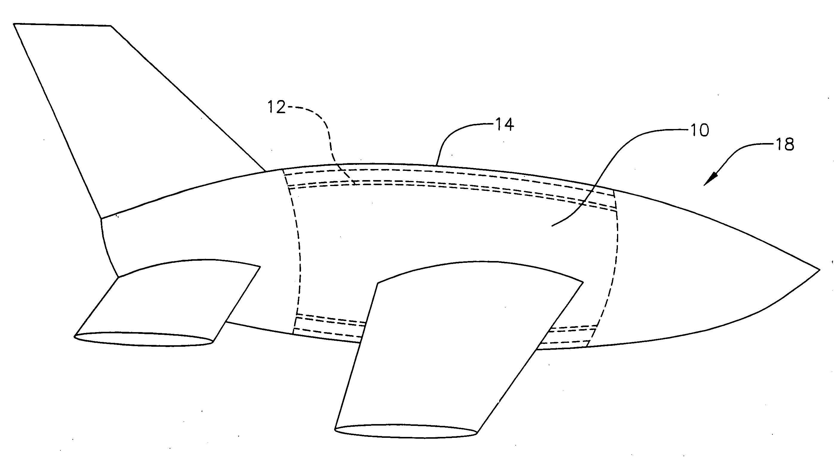
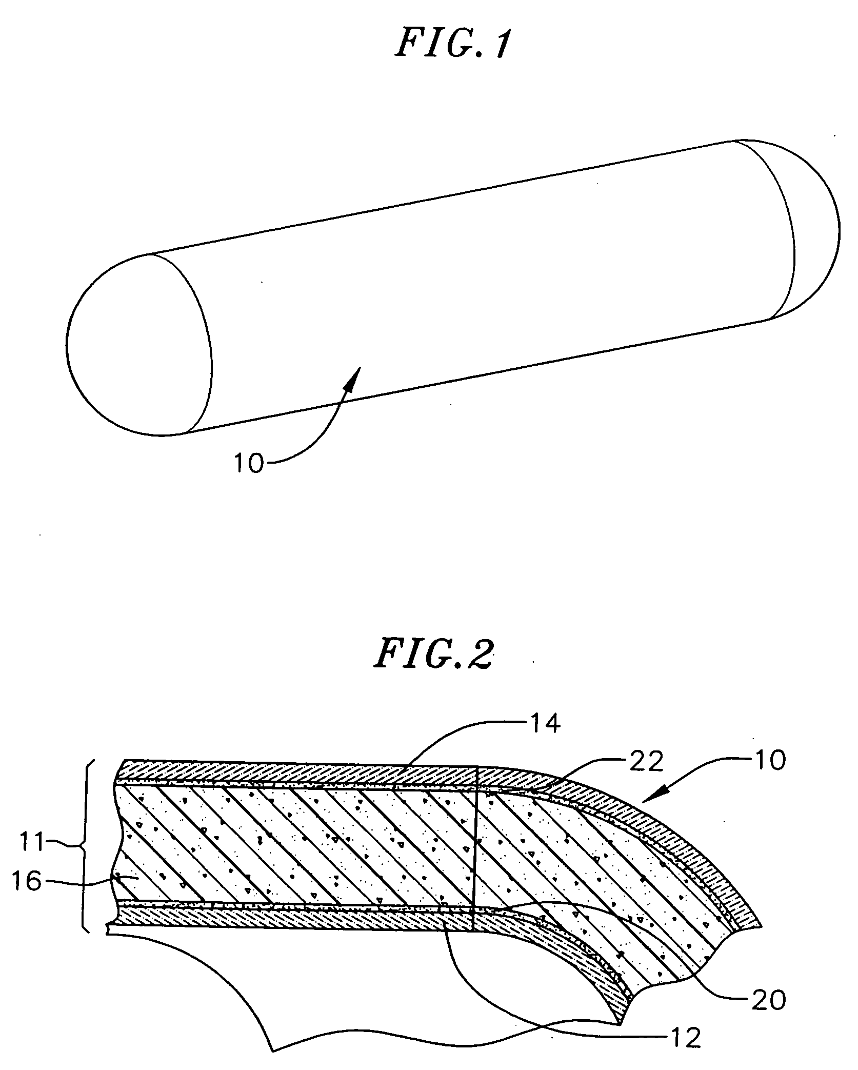
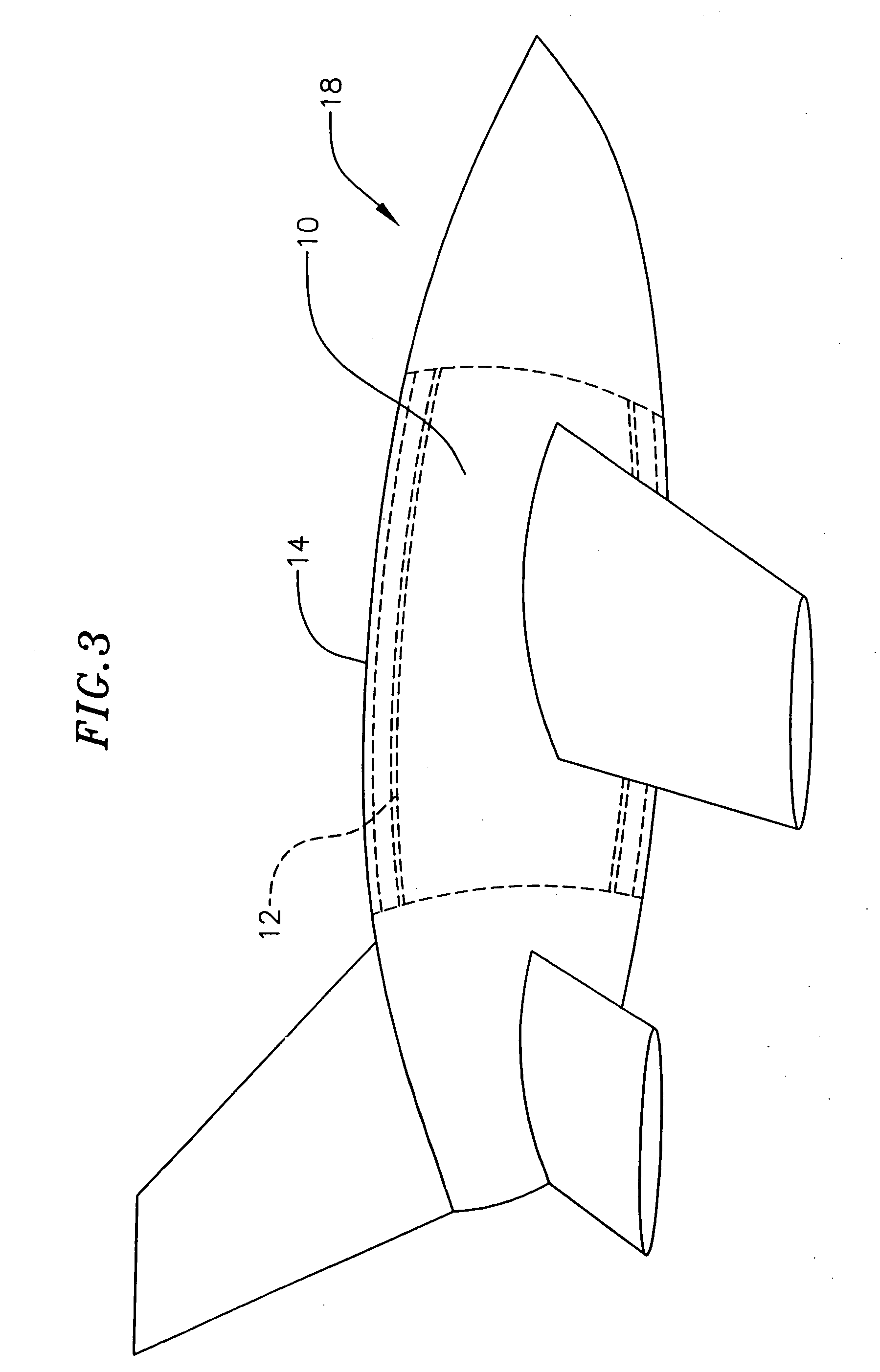
[0015]The present invention provides sandwich construction tanks for carrying cryogenic fluids, as for example shown in FIGS. 1 and 2, such as oxidizers, liquid hydrogen and liquid methane, as well as non-cryogenic fluids such as hydrogen peroxide. It should be noted that the figures are not to scale and are used only for illustrative purposes. In an exemplary embodiment shown in FIGS. 1 and 2, a cryogenic tank 10 is defined by a structural wall 11 which when viewed in cross-section includes an inner wall 12 separated from an outer wall 14 by an insulating material forming a core 16. By employing a sandwich construction, the tank inner wall and thus, the tank contents are insulated, and the tank inner wall 12 and outer wall 14 act together to form a rigid structural wall 11. The outer tank wall 14 is thermally isolated from the tank ...


PUM

PropertyMeasurementUnit
Poweraaaaaaaaaa
Elongationaaaaaaaaaa
Structureaaaaaaaaaa

Abstract

A tank for carrying cryogenic fluids and/or hydrogen peroxide and a method of forming the same is provided. A vehicle incorporating such a tank as part of the vehicle structure is also provided. The tank includes an inner wall compatible with the fluid to be carried, an outer wall, and a spacing layer sandwiched between the two walls. In an exemplary embodiment, the outer wall forms part of the structure of a flight vehicle.

Description

CROSS-REFERENCE TO RELATED APPLICATION(S)[0001]This application is a continuation of U.S. application Ser. No. 10 / 866,368, filed on Jun. 11, 2004, the contents of all of which are fully incorporated herein by reference.BACKGROUND OF THE INVENTION[0002]The present invention relates to tanks for storing cryogenic fluids and more specifically to tanks having a sandwich construction for storing a cryogenic fluid, to vehicles incorporating such tanks, and to methods for forming such tanks.[0003]Cryogenic tanks, i.e., tanks that carry or store cryogenic or chilled (referred to hereinafter collectively or individually as “cryogenic”) fluids are subject to significant contraction due to the temperature of the cryogenic fluids which could be in the range of about 18° K. to about 240° K. Cryogenic tanks are typically used in aerospace vehicles to carry various cryogenic fluids such as rocket propellant oxidizers and fuels. For example, cryogenic tanks are used on launch vehicles, upper stage ...

Claims


Application Information

Patent Timeline
IPC IPC(8): F17C3/04F17C13/00
CPCF17C3/04F17C2201/0104F17C2201/054F17C2201/056F17C2203/0304F17C2203/0629F17C2203/0648F17C2203/0663F17C2203/0673F17C2205/0119F17C2209/2163F17C2221/012F17C2221/033F17C2223/0161F17C2223/033F17C2270/0194F17C2270/0197Y02E60/321Y02E60/32
Inventor GREASON, JEFFREY K.DELONG, DANIEL L.FORGET, OLIVIER
Owner XCOR AEROSPACE
Why Eureka
Try Eureka