
System, method, and apparatus for extracting power from a photovoltaic source of electrical energy

a photovoltaic and electrical energy technology, applied in the direction of batteries, process and machine control, instruments, etc., can solve the problems of reducing the harvesting efficiency of the pv system, and generally much more complex maximum power tracking techniques

Inactive Publication Date: 2008-10-23
GENERAL ELECTRIC CO
View PDF9 Cites 85 Cited by
  • Summary
  • Abstract
  • Description
  • Claims
  • Application Information

AI Technical Summary

Benefits of technology

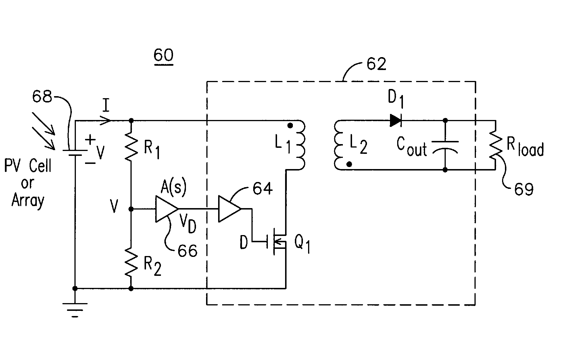
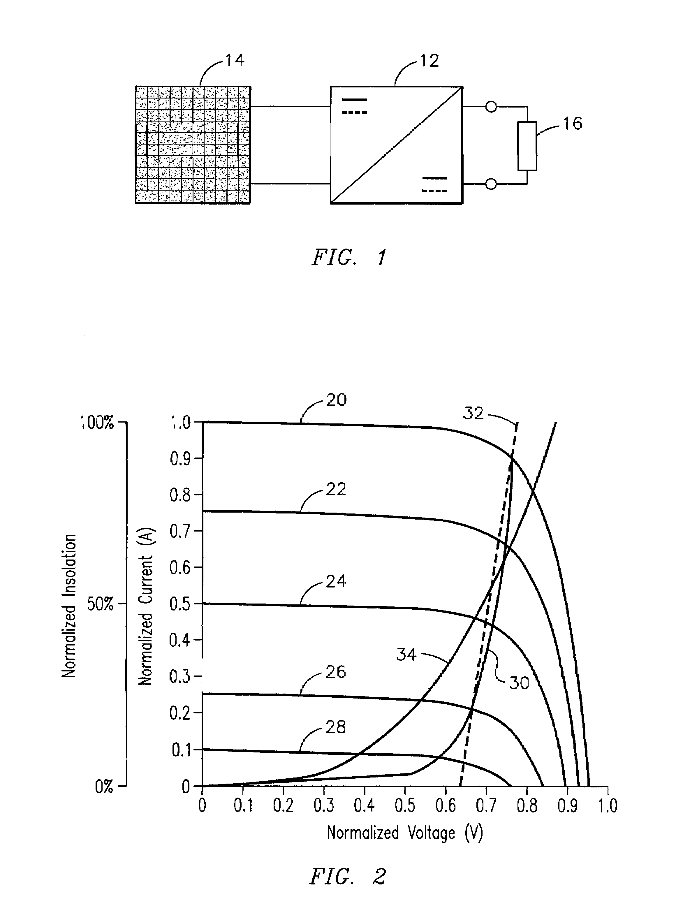
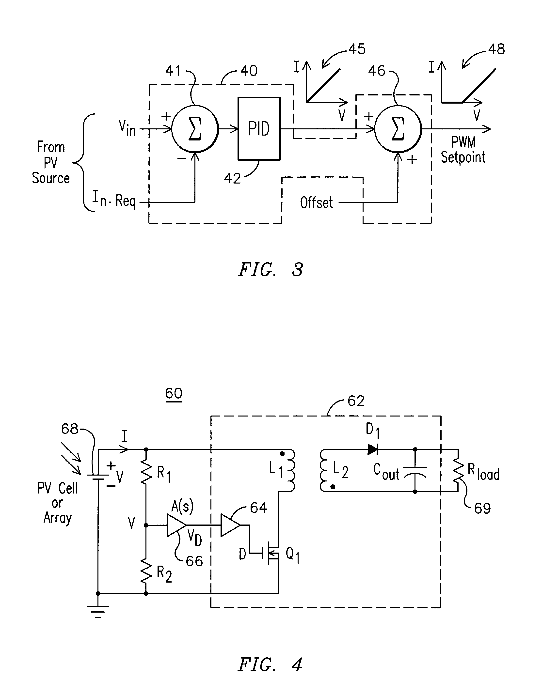
[0007]Generally, the present invention fulfills the foregoing needs by providing, in one aspect thereof, a photovoltaic system that includes a photovoltaic source of electrical energy. The photovoltaic source has power-generating characteristics defined by a family of voltage-current curves comprising points of maximum electrical power over a respective range of at least one of the following for the photovoltaic source: distinct illumination intensities and distinct temperatures. A switching converter is coupled to the photovoltaic source, wherein the converter comprises an input voltage-current curve having a predefined functional relationship between the input voltage and the input current. The predefined functional relationship of the input voltage-current curve of the converter is configured to provide during operation of the converter an approximation with respect to at least some of the points of maximum electrical power for the photovoltaic source without having to perform current and voltage calculations corresponding to a maximum power from the photovoltaic source.
[0008]In another aspect thereof, the present invention further fulfills the foregoing needs by providing a method for harvesting electrical power from a photovoltaic system. The method defines power-generating characteristics of a photovoltaic source of electrical energy by a family of voltage-current curves comprising points of maximum electrical power over a respective range of at least one of the following for the photovoltaic source: distinct illumination intensities and distinct temperatures. The method allows coupling a switching converter to the photovoltaic source, wherein the converter comprises an input voltage-current curve having a predefined functional relationship between the input voltage and the input current. The converter is operated to approximate at least some of the points of maximum electrical power for the photovoltaic source based on a configuration of the predefined functional relationship of the input voltage-current curve of the converter without having to perform current and voltage calculations corresponding to a maximum power from the photovoltaic source.
[0009]In yet another aspect thereof, the present invention further fulfills the foregoing needs by providing apparatus for harvesting electrical energy from a photovoltaic source of electrical energy. The photovoltaic source has power-generating characteristics defined by a family of voltage-current curves comprising points of maximum electrical power over a respective range of at least one of the following for the photovoltaic source: distinct illumination intensities and distinct temperatures. The apparatus comprises a switching converter coupled to the photovoltaic source, wherein the converter comprises an input voltage-current curve having a predefined functional relationship between the input voltage and the input current. The predefined functional relationship of the input voltage-current curve of the converter is configured to provide during operation of the converter an approximation with respect to at least some of the points of maximum electrical power for the photovoltaic source without having to perform current and voltage calculations corresponding to a maximum power from the photovoltaic source.

Problems solved by technology

In practice, however, there are some issues concomitant with maximum power tracking techniques.
First, the implementation of the tracking algorithm in a processor requires an incremental consumption of electrical power for powering such a processor, thus reducing harvesting efficiency of the PV system.
Second, maximum power tracking is generally much more complex than just regulating the switching converter to a reference and the switching operation of the converter can interfere with appropriately determining the maximum power point and, in some cases, is prone to operational instabilities while seeking to solve the maximum power point algorithm.
Third, power tracking algorithms commonly require sensing of both current and voltage of the PV source.
This current sensing often results in additional losses, thus further reducing the overall efficiency of the PV system.

Method used


Image

  • System, method, and apparatus for extracting power from a photovoltaic source of electrical energy
  • System, method, and apparatus for extracting power from a photovoltaic source of electrical energy
  • System, method, and apparatus for extracting power from a photovoltaic source of electrical energy

Examples


Embodiment Construction

[0017]The inventors of the present invention propose an innovative photovoltaic (PV) system and / or methodology that may be advantageously used to extract, under a wide variety of operational and / or environmental conditions, maximum or near-maximum electrical power from a source of electrical energy, such as photovoltaic (PV) power source, as may be made up of a single photovoltaic cell or a photovoltaic module in the case of a battery of cells. Advantageous aspects of the present invention eliminate the need of having to utilize maximum power tracking circuitry and control for such circuitry, and thus avoid issues concomitant with maximum power tracking circuitry or control. For example, aspects of the present invention avoid having to utilize processing means for implementing a maximum power tracking algorithm and lead to incremental savings of electrical power since one does not have to electrically power such processing means. Moreover, aspects of the present invention lead to in...


PUM


Abstract

System, method, and apparatus are provided for harvesting electrical energy from a photovoltaic source of electrical energy. The photovoltaic source has power-generating characteristics defined by a family of voltage-current curves comprising points of maximum electrical power over a respective range of at least one of the following for the photovoltaic source: distinct illumination intensities and distinct temperatures. The apparatus is made up of a switching converter coupled to the photovoltaic source. The converter has an input voltage-current curve having a predefined functional relationship between the input voltage and the input current. The predefined functional relationship of the input voltage-current curve of the converter is configured to provide during operation of the converter an approximation with respect to at least some of the points of maximum electrical power for the photovoltaic source without having to perform current and voltage calculations corresponding to a maximum power from the photovoltaic source.

Description

FIELD OF THE INVENTION[0001]The present invention is generally related to harvesting electrical power from a source of electrical energy, and, more particularly, to system and method for extracting, under a wide variety of operational and / or environmental conditions, maximum or near-maximum electrical power from a source of electrical energy, such as a photovoltaic (PV) power source, a fuel cell or a battery.BACKGROUND OF THE INVENTION[0002]For a given level of insolation (illumination intensity), a photovoltaic (PV) energy source may be characterized by a graph of current versus voltage, generally referred to as the current-voltage (I-V) curve. It is known that when the PV source is uniformly illuminated, then such a PV source typically has one unique value of current and voltage at which maximum electrical power can be extracted for a given illumination intensity and / or temperature.[0003]To extract maximum electrical power, an electrical load connected to the PV source must be adj...

Claims


Application Information

Patent Timeline
IPC IPC(8): H01L31/042
CPCG05F1/67Y10S136/293Y10S323/906Y02E10/58H02J2300/24H02J3/381Y02E10/56H02J2300/26H02J3/46
Inventor GLASER, JOHN STANLEYDE ROOIJ, MICHAEL ANDREW
Owner GENERAL ELECTRIC CO
Learn More