Flexible circuit structure with stretchability and method of manufacturing the same

Inactive Publication Date: 2008-10-23
IND TECH RES INST
View PDF13 Cites 61 Cited by
  • Summary
  • Abstract
  • Description
  • Claims
  • Application Information

AI Technical Summary

Benefits of technology

[0010]Accordingly, the present invention is mainly directed to a flexible circuit structure with stretchability and a method of manufacturing the same. By supporting a circuit with island-shaped flexible bumps, when a flexible substrate is deformed under an external force, the circuit has bette

Problems solved by technology

However, the external stresses are mainly withstood by the circuit structure directly, so that the stretchability of the circuit structure is limited.
Moreover,

Method used


Image

  • Flexible circuit structure with stretchability and method of manufacturing the same
  • Flexible circuit structure with stretchability and method of manufacturing the same
  • Flexible circuit structure with stretchability and method of manufacturing the same

Examples


first embodiment

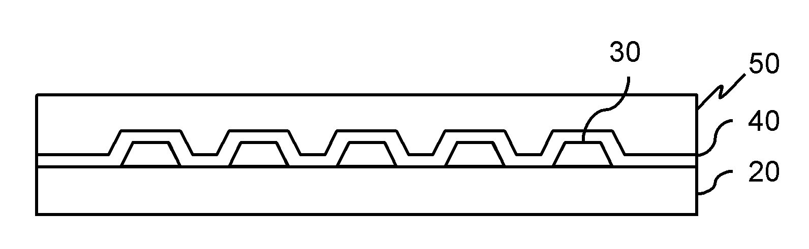
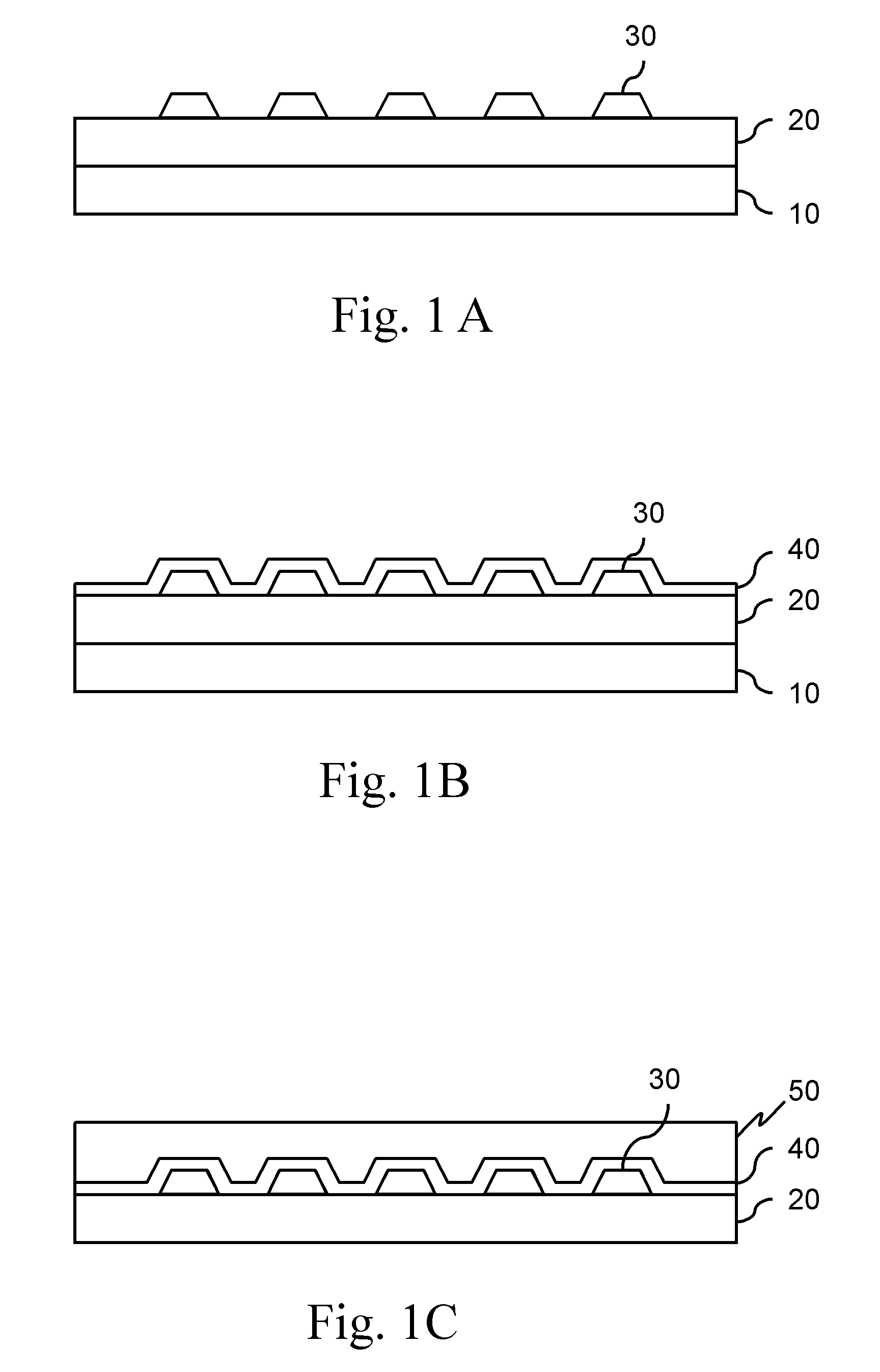
[0039]FIGS. 1A, 1B, and 1C are respectively schematic sectional views of a flexible circuit structure according to the present invention. As shown in FIG. 1C, the flexible circuit structure with stretchability of the present invention includes a flexible substrate 20, a plurality of flexible bumps 30, a metal layer 40, and a flexible material layer 50.

[0040]Firstly, as shown in FIG. 1A, in the flexible circuit structure with stretchability of the present invention, the flexible substrate 20 is attached on a supporting substrate 10 through a thermal release manner or a UV release manner. The material of the flexible substrate 20 includes polyimide (PI) or polydimethylsiloxane (PDMS). Then, a plurality of compressible flexible bumps 30 is deposited on the flexible substrate 20 at predetermined positions for implanting the metal circuit, and the compressibility of the flexible bumps 30 is higher than that of the flexible substrate 20. The material of the flexible bumps 30 includes poly...

second embodiment

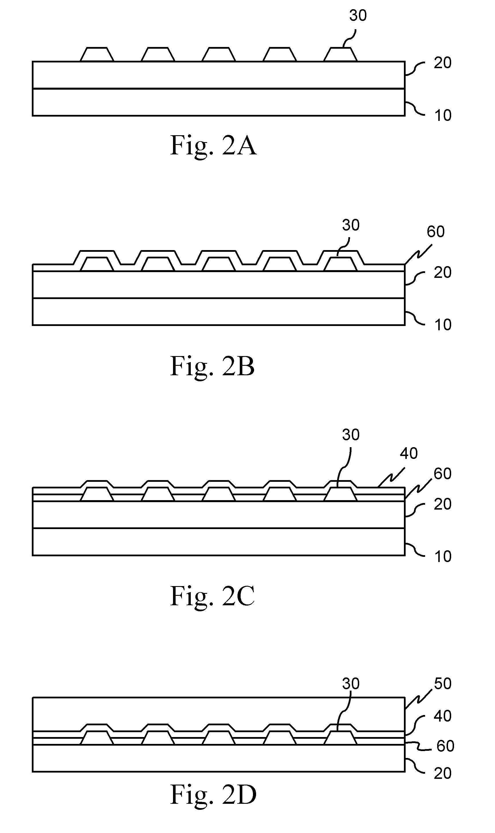
[0042]FIGS. 2A, 2B, 2C, and 2D are respectively schematic sectional views of a flexible circuit structure according to the present invention. As shown in FIG. 2D, the flexible circuit structure with stretchability of the present invention includes a flexible substrate 20, a plurality of flexible bumps 30, a metal layer 40, a flexible material layer 50, and a buffer layer 60.

[0043]Firstly, as shown in FIG. 2A, in the flexible circuit structure with stretchability of the present invention, the flexible substrate 20 is attached on a supporting substrate 10 through the thermal release manner or the UV release manner. The material of the flexible substrate 20 includes polyimide (PI) or polydimethylsiloxane (PDMS). Then, a plurality of compressible flexible bumps 30 is deposited on the flexible substrate 20 at predetermined positions for implanting the metal circuit, and the compressibility of the flexible bumps 30 is higher than that of the flexible substrate 20. The material of the flex...

fourth embodiment

[0046]FIGS. 4A, 4B, and 4C are respectively schematic sectional views of a flexible circuit structure according to the present invention. As shown in FIG. 4C, the flexible circuit structure with stretchability of the present invention includes a flexible substrate 20, a plurality of flexible bumps 30, a metal layer 40, a first flexible material layer 51, a second flexible material layer 52, an active element 70, and via holes 80.

[0047]Firstly, as shown in FIG. 4A, in the flexible circuit structure with stretchability of the present invention, the flexible substrate 20 is attached on a supporting substrate 10 through the thermal release manner or the UV release manner. The material of the flexible substrate 20 includes polyimide (PI) or polydimethylsiloxane (PDMS). Then, the active element 70 (e.g., a chip) is disposed on the surface of the flexible substrate 20 in a direction facing the flexible substrate 20. Next, the first flexible material layer 51 is implanted on the active elem...


PUM

PropertyMeasurementUnit
Flexibilityaaaaaaaaaa
Compressibilityaaaaaaaaaa
Stretchabilityaaaaaaaaaa

Abstract

A manufacturing method of a flexible circuit structure with stretchability includes the following steps. A plurality of compressible flexible bumps is formed on a flexible substrate; next, a metal circuit is formed on the flexible substrate and each of the compressible flexible bumps. When an external tensile force is applied on the flexible substrate, the capability of the metal circuit in withstanding the external tensile force is improved due to flexibility of the compressible flexible bumps, and thus, the stretchability of the flexible circuit is improved.

Description

CROSS-REFERENCE TO RELATED APPLICATIONS[0001]This non-provisional application claims priority under 35 U.S.C. § 119(a) on Patent Application No(s). 096113690 filed in Taiwan, R.O.C. on Apr. 18, 2007, the entire contents of which are hereby incorporated by reference.BACKGROUND OF THE INVENTION[0002]1. Field of the Invention[0003]The present invention relates to a flexible circuit structure and a method of manufacturing the same, and more particularly to a flexible circuit structure with stretchability and a method of manufacturing the same.[0004]2. Related Art[0005]Due to the developing trend of the electronics to become light, thin, short, and small and flexible, printed circuit boards (PCBs) that cannot be bent have gradually been replaced by highly-plastic flexible printed circuits (FPCs) boards, e.g., E-papers or flexible displays. In the applications of the FPC boards, the circuits must have specially-designed structures or made of special materials to withstand an external tens...

Claims


Application Information

Patent Timeline
IPC IPC(8): H05K1/00H05K1/03H05K3/00
CPCH01L23/49816Y10T29/49124H05K1/0283H05K1/185H05K1/189H05K3/007H05K2201/0133H05K2201/0367H05K2201/09263H05K2201/09909H05K2203/016H05K2203/0271H01L2924/0002H01L23/4985H01L2924/00
Inventor CHEN, YU-HUASHIH, YING-CHING
Owner IND TECH RES INST
Why Eureka
Try Eureka