Transmission oil pan

a transmission oil pan and oil pan technology, applied in mechanical equipment, gearing details, transportation and packaging, etc., can solve the problems of unfavorable loss of transmission function due to inadequate atf level and oil leakage related to cooling system, so as to reduce system cost, reduce cost and system complexity, and improve transmission efficiency

Inactive Publication Date: 2008-10-23
FORD GLOBAL TECH LLC
View PDF22 Cites 24 Cited by
  • Summary
  • Abstract
  • Description
  • Claims
  • Application Information

AI Technical Summary

Benefits of technology

[0007]Coolant is supplied to the transmission oil pan instead of sending ATF to a cooler at the front of the vehicle, thereby producing important advantages. ATF never leaves the transmission; therefore, oil leaks related to the cooling system and loss of transmission function due to inadequate ATF level are unlikely. In addition, the transmission operates more efficiently because its pump is not burdened with flow restrictions in cooler lines and the cooler.
[0008]Eliminating the oil-to-air cooler reduces system cost, results in the deletion of the cooler by-pass valve, which also reduces cost and system complexity, and improves air flow through the engine cooler & radiator at front of vehicle.
[0010]Fewer hydraulic connections are required between the engine & transmission cooling systems, thereby reducing cost and improving ease of assembly. Overall vehicle packaging space is improved, except for a deeper transmission oil pan.

Problems solved by technology

ATF never leaves the transmission; therefore, oil leaks related to the cooling system and loss of transmission function due to inadequate ATF level are unlikely.

Method used


Image

  • Transmission oil pan
  • Transmission oil pan
  • Transmission oil pan

Examples


Embodiment Construction

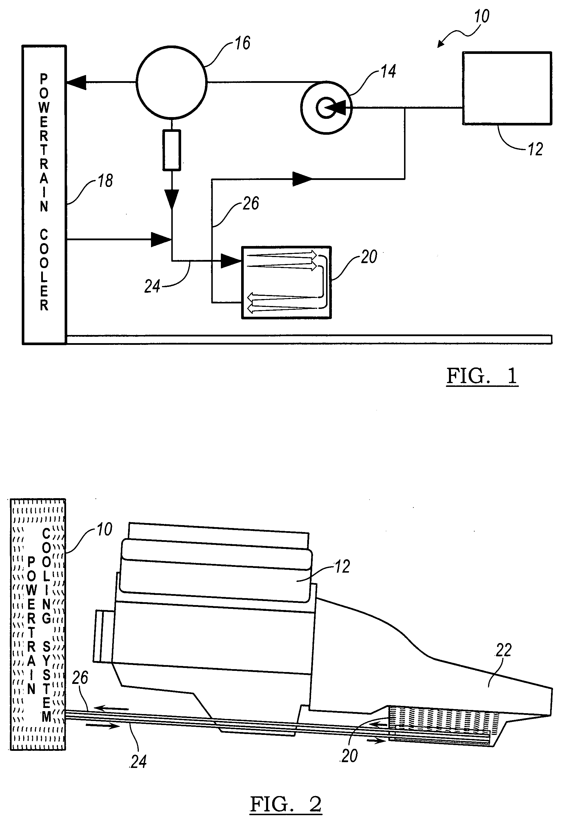
[0018]Referring first to FIG. 1, a cooling system for a vehicle powertrain 10 includes a coolant reservoir 12, a hydraulic pump, thermostat 16, cooler 18, and transmission oil pan 20 with integrated cooling. Engine coolant is drawn by pump 14 from reservoir 12, such as the water jacket of an engine block, and is supplied through thermostat 16 to cooler 18, where heat is exchanged from the coolant to an air stream flowing through cooler 18. Low temperature coolant exiting cooler 18 flows through oil pan 20, where heat is exchanged from transmission oil located in the oil pan 20 to the coolant. Upon exiting the oil pan 10, the coolant returns to pump 14, and is recirculated through the system 10.

[0019]FIG. 2 shows the engine block 12, the oil pan 20 secured to the bottom of a transmission case 22, an inlet line 24 that carries coolant from cooler 18 to the oil pan, and an outlet line 26 that returns coolant from the oil pan to the cooling system 10.

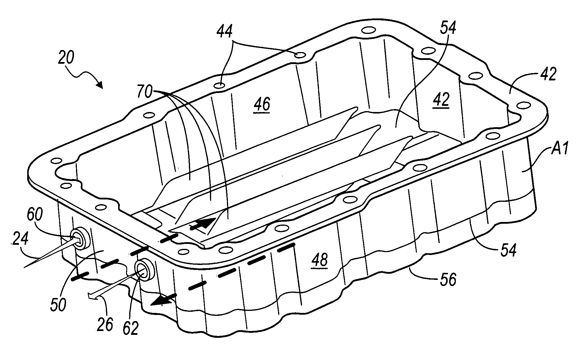
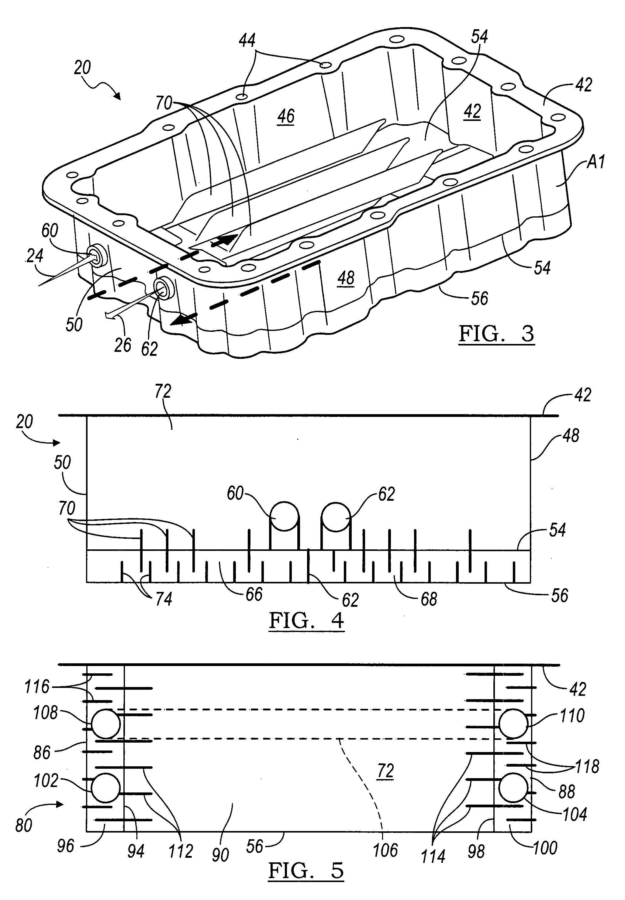
[0020]Referring to FIGS. 3 and 4, oi...


PUM


Abstract

An oil pan includes a chamber for containing a liquid, a first passage for containing a coolant and forming a first flow path along a length of the chamber, including a first surface located between the chamber and the first passage, and a second passage for containing the liquid coolant, communicating with the first passage and forming a second flow path along a length of the chamber, including a second surface located between the chamber and the second first passage.

Description

BACKGROUND OF THE INVENTION[0001]1. Field of the Invention[0002]This invention relates generally to cooling transmission fluid, and, more particularly, to an automatic transmission oil pan having an oil-to-coolant heat exchanger.[0003]2. Description of the Prior Art[0004]Automatic transmission fluid (ATF) circulates continually through the transmission lubricating and cooling components that rotate at relatively high speed within a transmission case. The ATF, which is drawn by a pump from a transmission sump or oil pan located below, and secured to the transmission case, returns to the oil pan by gravity feed after circulating through the transmission. Its temperature increases in this flow path and must be lowered by passing through an oil cooler, which is usually located behind a radiator, in which heat from the engine coolant is transferred to an air stream flowing through the radiator. The system that supports this heat exchange consumes packaging space, is inefficient, costly, ...

Claims


Application Information

Patent Timeline
Patent Type & Authority Applications(United States)
IPC IPC(8): B62D25/20
CPCF01M11/0004F01M2011/0025F01M2011/0066F16H57/0412F16H57/0452
Inventor STRANGES, ANTONIO
Owner FORD GLOBAL TECH LLC
Why Eureka
Try Eureka