Support and extension rail assembly

a technology for electrical switching apparatus and extension rails, which is applied in the direction of electrical apparatus construction details, switchgear with a retractable carriage, and show shelves, etc., can solve the problems of affecting the operation certain types of electrical switching apparatus, and known high loads during operation, so as to achieve effective load transfer

Active Publication Date: 2008-10-23
EATON INTELLIGENT POWER LIMITED
View PDF13 Cites 1 Cited by
  • Summary
  • Abstract
  • Description
  • Claims
  • Application Information

AI Technical Summary

Benefits of technology

[0020]The support rail assembly body further includes protrusions on the exterior surface that are structured to be disposed in openings with a corresponding shape in the housing assembly. The protrusions are, preferably, cast as part of the support rail assembly body. The protrusions have a cross-sectional area that is larger than, for example, a bolt or screw. As such, the protrusions more effectively transfer loads from the electrical device supported by the rails to the housing assembly.

Problems solved by technology

Certain types of electrical switching apparatus have a considerable weight.
Further, certain types of electrical switching apparatus, such as, but not limited to, a circuit breaker having a high interruption capability, are known to experience high loads during operation.
While not incorporating rail extensions into each housing assembly does reduce the cost of a housing assembly, this configuration may result in the rail extension not being available when needed.
Such coupling structures are not efficient for transferring loads from the electrical switching apparatus to the housing assembly and, typically, require the use of additional support plates.
Such mechanisms are difficult to actuate when users are wearing protective gloves.

Method used


Image

  • Support and extension rail assembly
  • Support and extension rail assembly
  • Support and extension rail assembly

Examples


Embodiment Construction

[0030]As used herein, directional words and phrases, such as, but not limited to, “upper,” lower,”“interior,” and “exterior” relate to a housing assembly as shown in the figures. For example, a plate disposed entirely with the housing assembly may have an “exterior surface” which is the surface that is closest to the outside of the housing assembly.

[0031]As used herein, the word “unitary” means a component created as a single piece or unit. That is, a component that includes pieces that are created separately and then coupled together as a unit is not a “unitary” component or body.

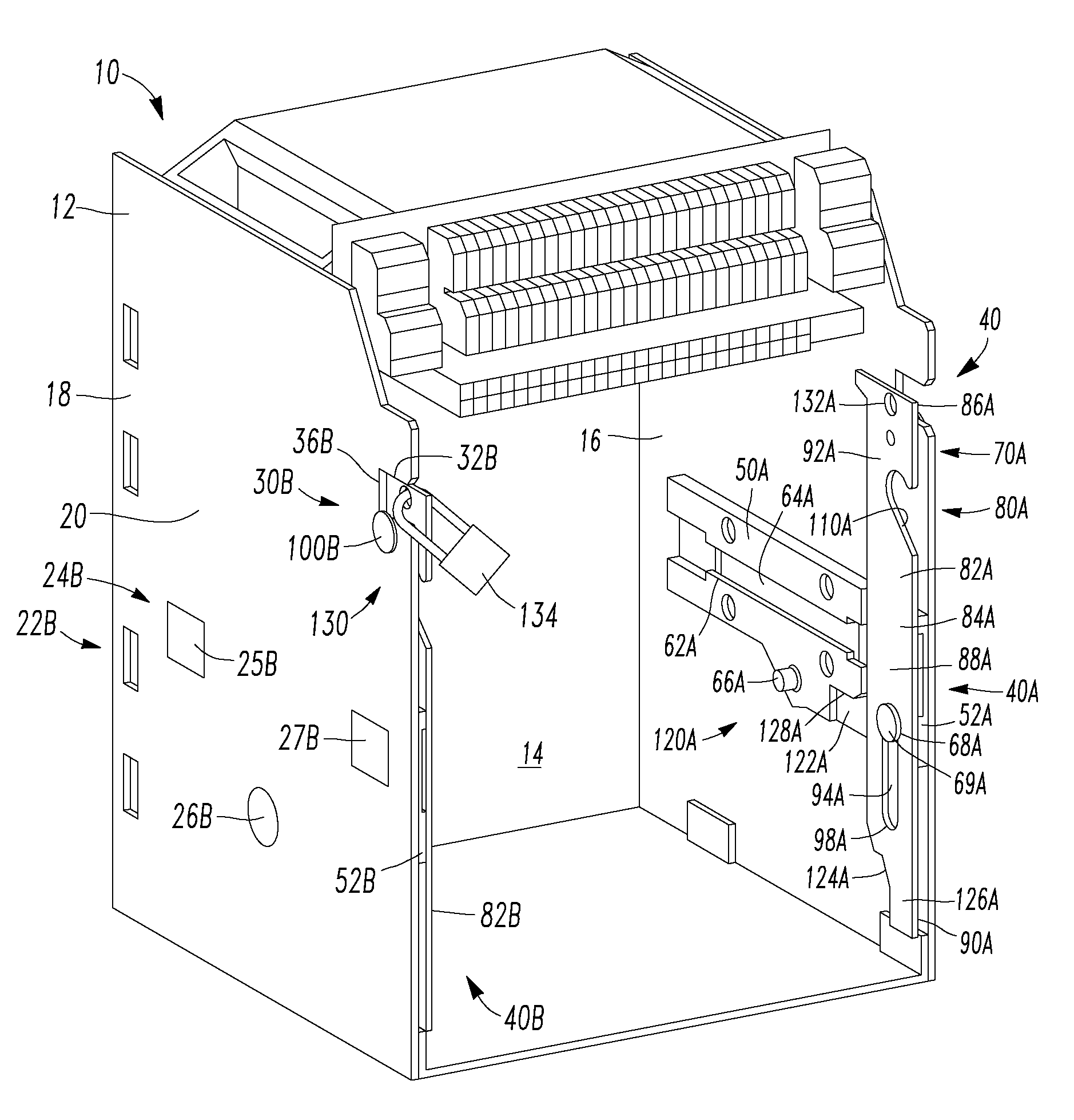
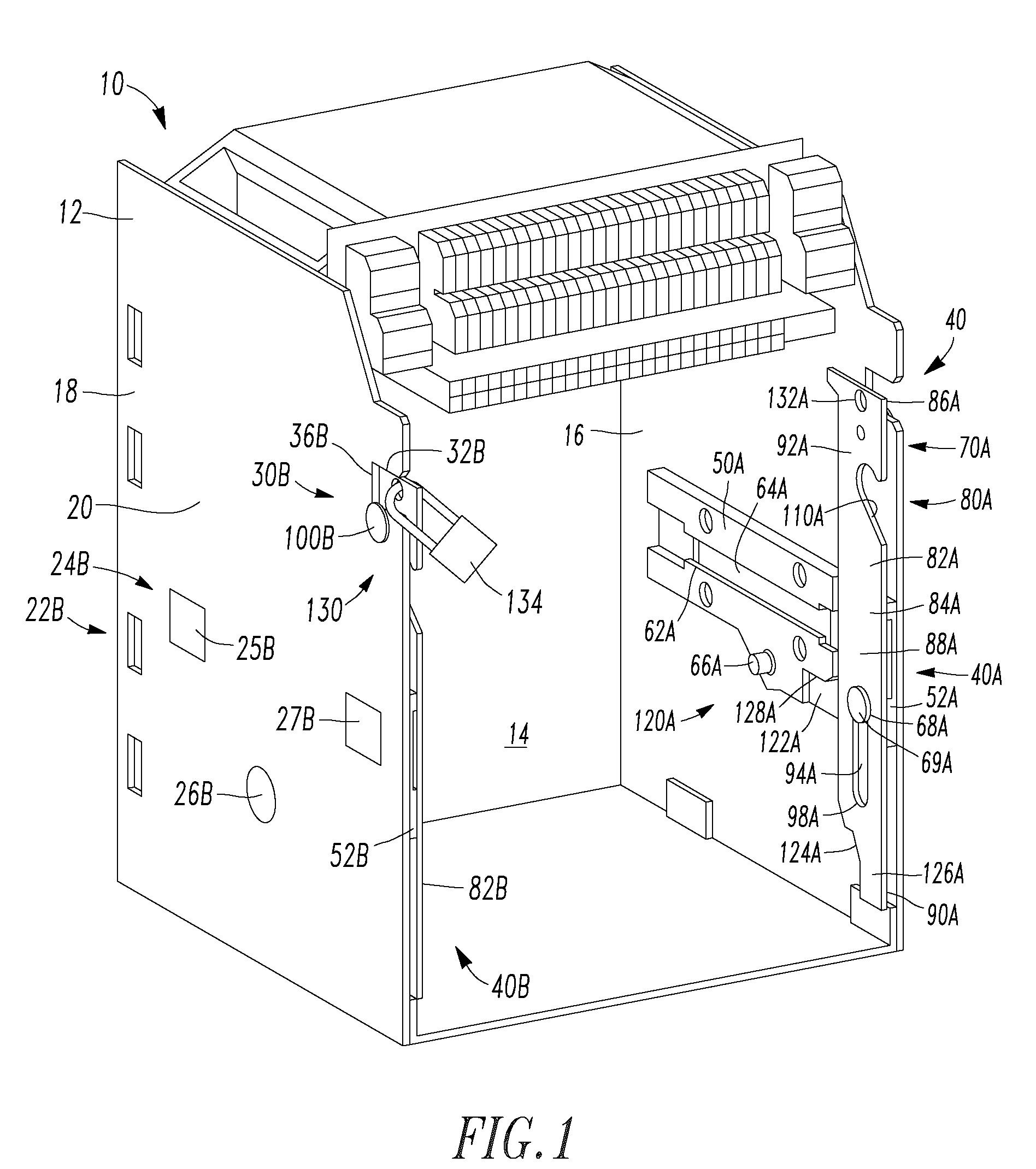
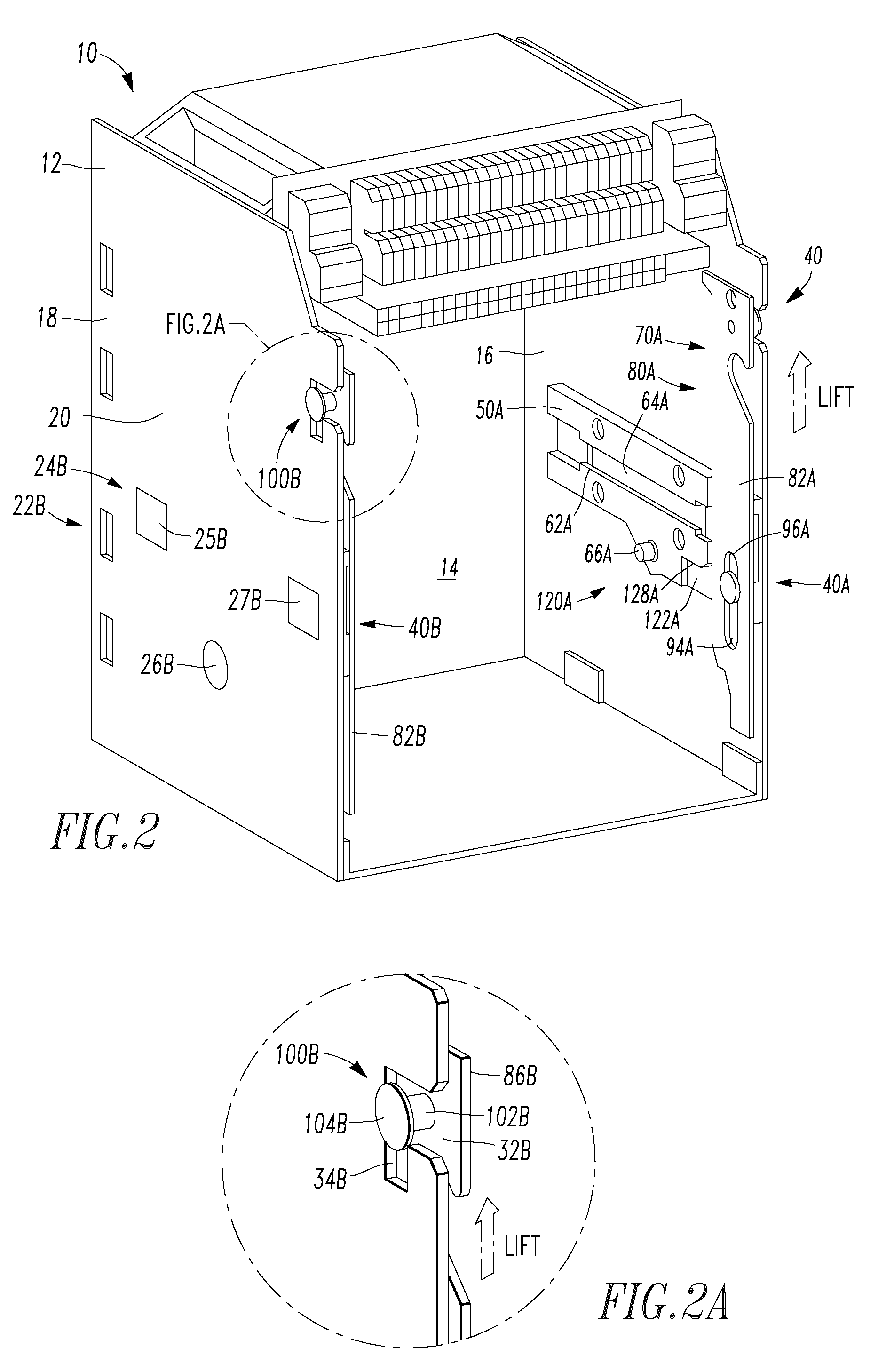
[0032]As shown in FIGS. 1-4, a housing assembly 10 for an electrical switching apparatus (not shown) includes a plurality of sidewalls 12 defining an enclosed space 14. Typically, the plurality of sidewalls 12 include six sidewalls disposed in a rectangular box-like configuration. It is noted that a front sidewall, which may be a door or a removable sidewall, is not shown. Such a front sidewall is well kno...


PUM


Abstract

A housing assembly and a support rail and extension rail assembly for an electrical switching apparatus includes various components. The support rail assembly is, preferably, a cast plate-like body wherein selected components, such as a levering in mechanism lug and support rails are formed as part of the casting. The extension rail assembly includes a generally flat, elongated body having a finger notch that is sized to accommodate a gloved hand and a mounting slot. The extension rail assembly is coupled to the support rail assembly by a pivotal mounting that extends through the mounting slot. The extension rail further includes a lateral extension. The housing assembly includes an L-shaped cutout having a horizontal portion and a descending vertical portion. When the extension rail is in a storage, or first, position, the lateral extension is disposed in the L-shaped cutout.

Description

BACKGROUND OF THE INVENTION[0001]1. Field of the Invention[0002]This invention relates to a housing assembly for an electrical switching apparatus and, more specifically, to an extension rail assembly for an electrical switching apparatus housing assembly.[0003]2. Background Information[0004]An electrical switching apparatus is typically disposed in a housing assembly. The housing assembly is, typically, a rectangular box having a back sidewall, a top sidewall, a bottom sidewall, a right sidewall, a left sidewall, and a front sidewall. Selected sidewalls, typically the back sidewall or the top and bottom sidewalls, have openings therethrough which are structured to accommodate the line and load conductors for the electrical switching apparatus. The front sidewall may be movable, or removable, so as to allow access to the enclosed space defined by the housing assembly. An electrical switching apparatus may be disposed in the enclosed space defined by the housing assembly and coupled ...

Claims


Application Information

Patent Timeline
Patent Type & Authority Applications(United States)
IPC IPC(8): H05K7/02
CPCH02B11/127
Inventor OSTROWSKI, FRANKIE K.GUNDY, RAYMOND P.KOZAR, AARON T.OLSZEWSKI, DAVID M.
Owner EATON INTELLIGENT POWER LIMITED
Why Eureka
Try Eureka