Vehicle headlight device

a headlight device and vehicle technology, applied in the direction of electric variable regulation, process and machine control, instruments, etc., can solve the problems of vehicle running in a dead-dark condition, others will not be aware of the presence of the vehicle, etc., to facilitate the assembly of the vehicle headlight device and improve the safety of traveling

Inactive Publication Date: 2008-10-23
KOITO MFG CO LTD
View PDF13 Cites 15 Cited by
  • Summary
  • Abstract
  • Description
  • Claims
  • Application Information

AI Technical Summary

Benefits of technology

[0009]One or more embodiments of the present invention inhibit an infrared ray from being emitted in an abnormal situation of a power supply or a lower beam.
[0011]The control circuit commands the upper beam / infrared ray switching unit to illuminate the upper beam or the infrared ray when the lower beam and the power supply voltage are in their normal state, and also the control circuit inhibits the upper beam / infrared ray switching unit from illuminating the infrared ray in response to the infrared ray stop signal from the infrared ray stop signal generating circuit when the lower beam or the power supply voltage is brought into an abnormal state in a situation that the lower beam must be illuminated. Therefore, it can be prevented that only the infrared ray is emitted in a situation that the lower beam should be emitted and, thus, this device can contribute to improvement of safety in traveling.
[0013]The infrared ray stop signal generating circuit is constructed by two sets of electronic circuits each of which is formed of a transistor and resistors, the first infrared ray stop signal as the output of one electronic circuit and the second infrared ray stop signal as the output of the other electronic circuit are output to the control circuit via one signal line respectively. Therefore, the first infrared ray stop signal and the second infrared ray stop signal can be transmitted with a simple electronic circuit via one signal line and, thus, a simplification of the circuit configuration can be attained.
[0015]The lower beam lighting circuit, the low-beam abnormality detecting circuit, and the power-supply abnormality detecting circuit are constructed integrally to lighten the lower beam or to detect the abnormality of the power supply or the lower beam. Therefore, there is no need to provide additional circuit units and, thus, assembling of the vehicle headlight device can be facilitated.
[0016]As apparent from the above explanation, according to the vehicle headlight device according to one or more embodiments, it can be prevented that only the infrared ray is emitted in a situation that the lower beam should be emitted and, thus, this device can contribute to improvement of safety in traveling.
[0018]According to one or more embodiments, there is no need to provide additional circuit units and, thus, assembling of the vehicle headlight device can be made easily.

Problems solved by technology

However, in the prior art, when the abnormality such as disconnection, failure, or the like occurs in the low-beam lamp in a situation that the illumination light is switched from the upper beam to the infrared ray, the vehicle is able to run in a dead-dark condition in which no upper beam is illuminated, i.e., a condition that only the infrared ray is illuminated and the image picked up by the infrared ray CCD camera is displayed on the display.
In this case, because the infrared ray is invisible to the human eye, it is feared that others will not be aware of the presence of the vehicle.
Also, even when the abnormality occurs in the battery voltage, the lamp lighting circuit does not stop the illumination of the infrared ray that is invisible to the human eye.

Method used


Image

  • Vehicle headlight device
  • Vehicle headlight device
  • Vehicle headlight device

Examples


Embodiment Construction

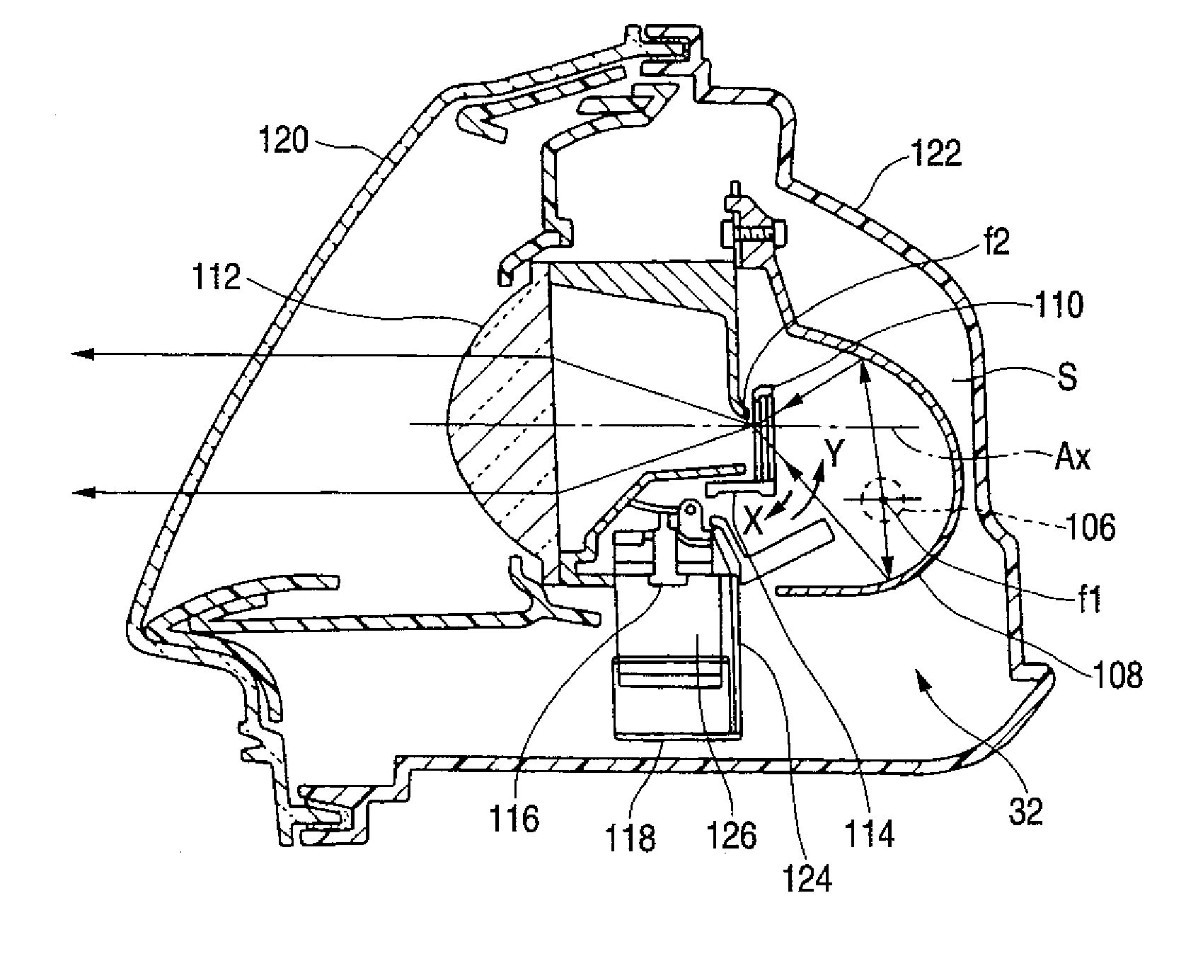
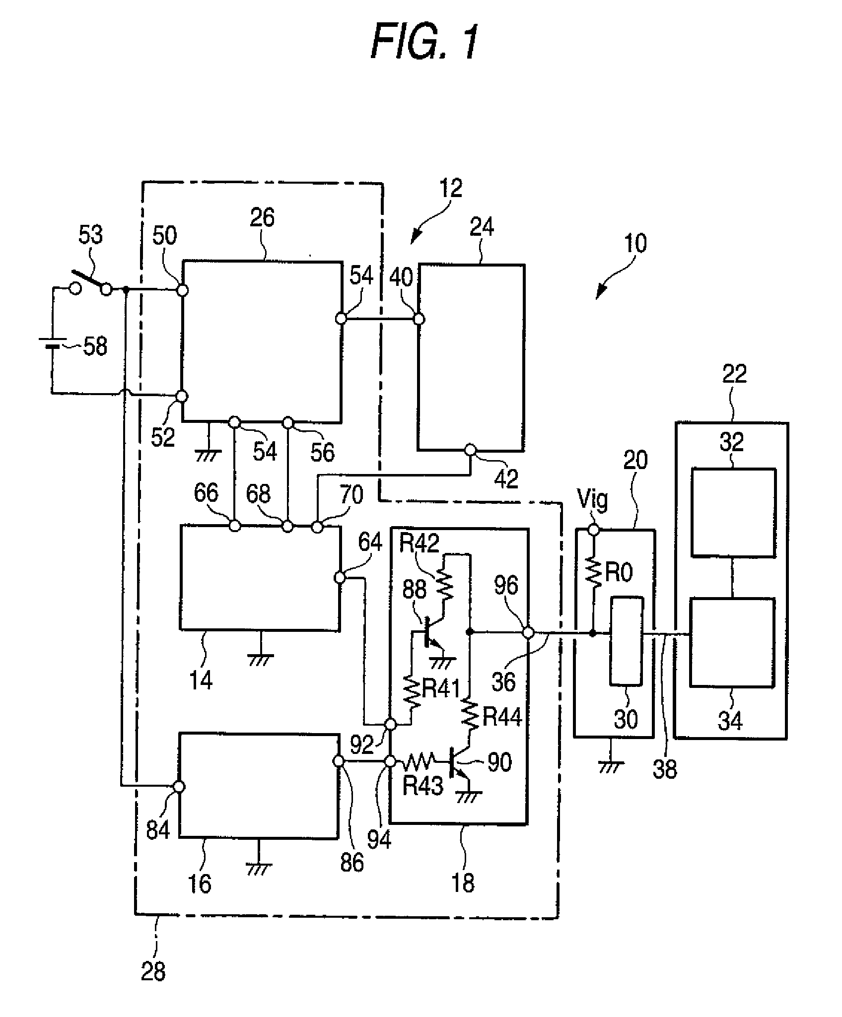
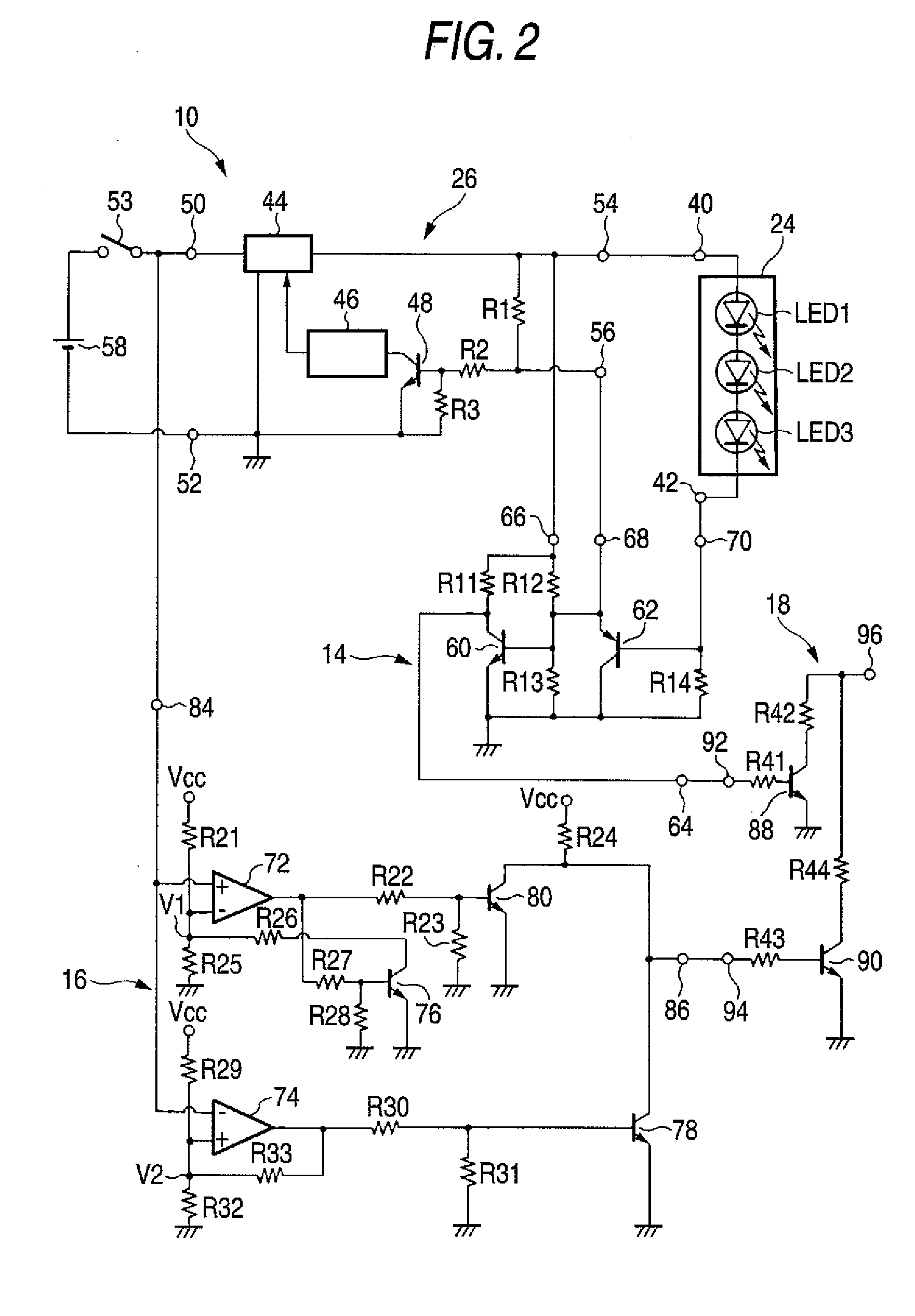
[0025]Embodiments of the present invention will be explained with reference to the drawings hereinafter. FIG. 1 is a configurative block diagram of a vehicle headlight device showing an embodiment of the present invention, FIG. 2 is a pertinent configurative circuit diagram of the vehicle headlight device, FIG. 3 is a configurative block diagram of a control circuit, FIG. 4 is a sectional view of an upper beam / infrared ray light source unit, and FIG. 5 is a configurative circuit diagram of an infrared ray transmission filter driving circuit.

[0026]In FIG. 1, a vehicle headlight device 10 is constructed to have a lower beam unit 12, a low-beam abnormality detecting circuit 14, a power-supply abnormality detecting circuit 16, an infrared ray stop signal generating circuit 18, a control unit 20, and an upper beam / infrared ray switching unit 22.

[0027]The lower beam unit 12 is constructed by a low-beam light source block 24, and a lower beam lighting circuit 26. The lower beam lighting ci...


PUM


Abstract

A vehicle headlight device includes a lower beam unit for illuminating a lower beam, an upper beam / infrared ray switching unit for switching between illuminating an upper beam and an infrared ray, a low-beam abnormality detecting circuit for detecting an abnormality of the lower beam unit, a power-supply abnormality detecting circuit for detecting an abnormality of a power supply of the vehicle headlight, and a control circuit that inhibits the upper beam / infrared ray switching unit from illuminating the infrared ray when an abnormality is detected by either the low-beam abnormality detecting circuit or the power-supply abnormality detecting circuit.

Description

BACKGROUND OF INVENTION[0001]1. Field of the Invention[0002]The present invention relates to a vehicle headlight device installed into a vehicle to illuminate a front area of the vehicle and, more particularly, a vehicle headlight device using a bulb for emitting visible light and a bulb for emitting an infrared ray as a light source.[0003]2. Background Art[0004]As the vehicle headlight device, for example, such a device has been proposed that the halogen lamp for emitting an upper beam of visible light is employed as the high-beam light source. An infrared ray forming globe for shielding the visible light and transmitting infrared rays only is arranged movably with respect to the high-beam light source. The use of the upper beam and the infrared ray is switched by selecting one of a mode in which the infrared ray forming globe covers the high-beam light source, and a mode in which the infrared ray forming globe is moved ahead of the high-beam light source and the situation located ...

Claims


Application Information

Patent Timeline
Patent Type & Authority Applications(United States)
IPC IPC(8): B60Q1/00
CPCB60Q1/0088B60Q1/143B60Q11/005
Inventor NOYORI, YASUSHIKITAGAWA, TAKAYOSHI
Owner KOITO MFG CO LTD
Why Eureka
Try Eureka