LED light extraction bar and injection optic for thin lightguide

a technology of lightguide and injection optic, which is applied in the field of lightguides, can solve the problems of weak light spread, limited optical spread angle of propagation in the plane of lightguide, and poor uniformity

Inactive Publication Date: 2008-10-23
3M INNOVATIVE PROPERTIES CO
View PDF51 Cites 62 Cited by
  • Summary
  • Abstract
  • Description
  • Claims
  • Application Information

AI Technical Summary

Problems solved by technology

However, the optical spread angle for propagation in the plane of the lightguide is limited by the critical angle of light in the lightguide.
Therefore, the light spreads weakly and uniformity suffers.
Four deficiencies of conventional approaches may be summarized as:1. Air-coupling from the LED package into the lightguide restricts the angles of injected light to a propagation cone bounded by the critical angle of the lightguide, therefore, the light mixing region in the lightguide is lengthened.2. The standard LED packages are large; therefore the emitted light does not couple efficiently into a thin lightguide.3. The refractive index of the encapsulant is typically much lower than that of the emissive LED die; therefore the extraction of light from the die is inefficient.4. The LED lies in a plane that is parallel to the input edge of the lightguide.
As a result, conductive heat extraction is limited and difficult to implement.

Method used


Image

  • LED light extraction bar and injection optic for thin lightguide
  • LED light extraction bar and injection optic for thin lightguide
  • LED light extraction bar and injection optic for thin lightguide

Examples


Embodiment Construction

[0025]The present invention is applicable to optical systems and is more particularly applicable to optical display systems in which the display panel is illuminated from behind using a lightguide. In such displays, the light source or sources, is placed to the side of the display panel and the lightguide is used to transport the light from the light source(s) to positions behind the display panel. The invention relates to an approach for coupling light into the lightguide from a light source, such as a light emitting diode (LED).

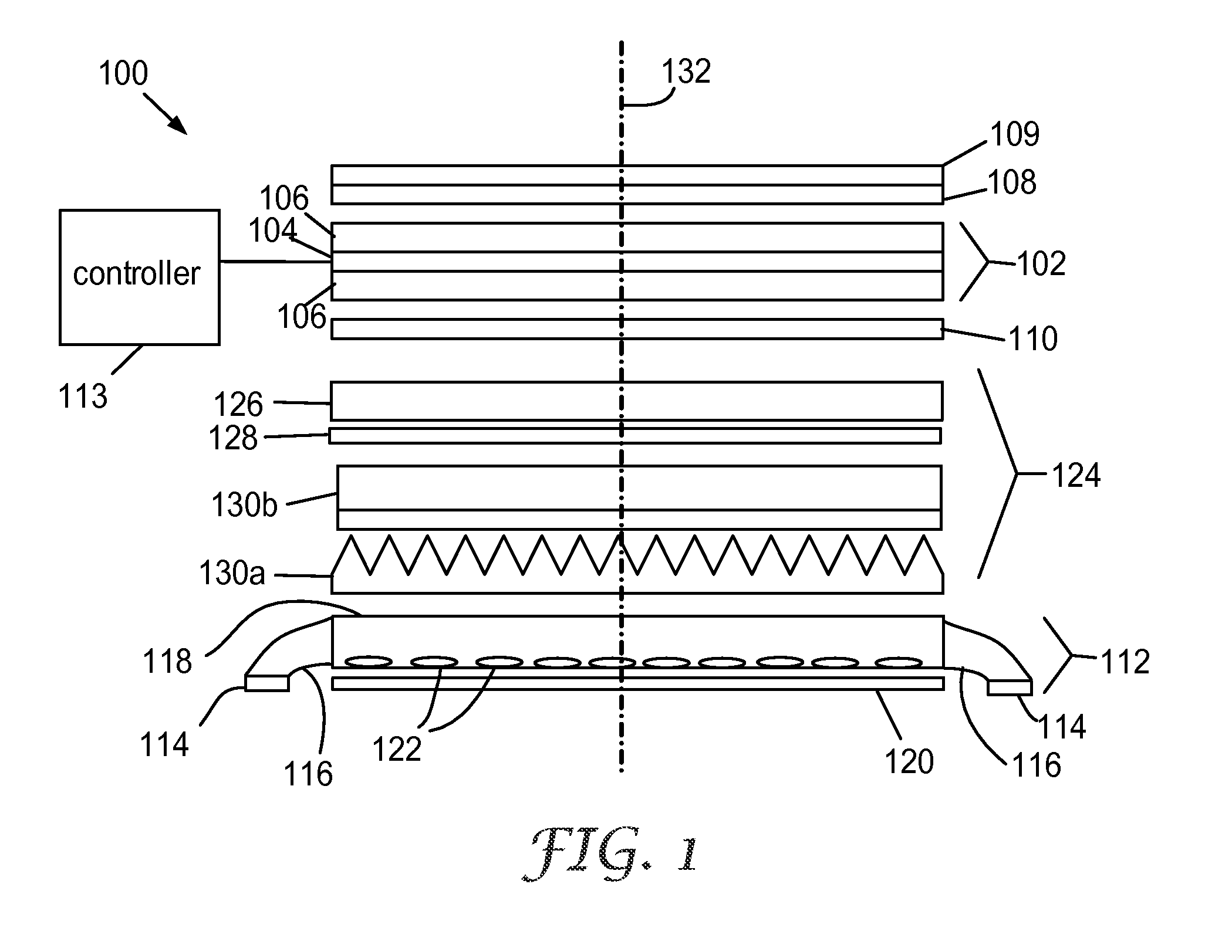
[0026]A schematic exploded view of an exemplary embodiment of an edge-lit display device 100 is presented in FIG. 1. In this exemplary embodiment, the display device 100 uses a liquid crystal (LC) display panel 102, which typically comprises a layer of LC 104 disposed between panel plates 106. The plates 106 are often formed of glass, or another stiff material, and may include electrode structures and alignment layers on their inner surfaces for controlling...


PUM


Abstract

An optical system for back-illuminating a display has a lightguide having a confinement direction and a first plurality of light sources disposed proximate a first edge of the lightguide. Light from at least one of the light sources defines an emission axis which is approximately parallel to the confinement direction. A solid light injector is disposed to couple light from the light sources into the lightguide. A surface of the light injector may be shaped as a confinement curve for confining light from the first plurality of light sources in the confinement direction by total internal reflection. In some embodiments a portion of the illumination light from the one or more light sources enters the first light injector along a direction having a component directed away from the lightguide and is totally internally reflected within the injector.

Description

FIELD OF THE INVENTION[0001]The invention relates to lightguides that are used, for example, for illuminating a display, and more particularly to methods and devices for injecting light into the lightguides from light emitting diodes.BACKGROUND[0002]The light emitting diode (LED) first gained entry to backlighting liquid crystal displays (LCDs) in small handheld displays. Such backlights typically comprise a lightguide with one or more white LEDs configured to inject light into one edge or one corner of the lightguide. Surface mount side-emitting LEDs for handheld backlights typically have an emission aperture 0.6 to 0.8 mm in height. Thus, the thinnest lightguide that will accept all of the light is 0.6 mm or thicker.[0003]In a handheld backlight the LED package is oriented beside the input edge of the lightguide and the light is coupled through air from the LED to the lightguide. An optical scattering surface is patterned on the bottom of the lightguide to extract light by directi...

Claims


Application Information

Patent Timeline
Patent Type & Authority Applications(United States)
IPC IPC(8): G02B6/26
CPCG02B6/0018G02B6/0028G02B6/0031G02B6/0068G02B6/0073G02B6/00G02B6/0001G02F1/1335
Inventor EPSTEIN, KENNETH A.
Owner 3M INNOVATIVE PROPERTIES CO
Why Eureka
Try Eureka