Counter-rotating axial-flow fan

a technology of axial flow fan and axial bore, which is applied in the direction of machines/engines, stators, liquid fuel engines, etc., can solve the problems of insufficient coupling between and the fitting portions of the first and second divided housing units are applied with excessive force, so as to prevent the breakage of the engagement portion between the engaging member and the engaged member

Inactive Publication Date: 2008-10-23
SANYO DENKI CO LTD
View PDF8 Cites 12 Cited by
  • Summary
  • Abstract
  • Description
  • Claims
  • Application Information

AI Technical Summary

Benefits of technology

[0018]In the present invention, the engaging member integrally formed with the first flange portion and the engaged member integrally formed with the second flange portion are employed for the coupling structure that couples the first divided housing unit and the second divided housing unit. The coupling of the first divided housing unit and the second divided housing unit are attained not only by a fitting structure constituted from the fitting portion of the first cylindrical air-channel half-portion and the engaged portion of the second cylindrical air-channel half-portion, but also by an engagement structure constituted from the engaging member and the engaged member. As a result, no force concentration will occur at the fitting structure of the first cylindrical air-channel half-portion and the second cylindrical air-channel half-portion. Moreover, the first and second divided housing units will not be readily decoupled or disconnected. In addition, in the present invention, the first stopper portions are provided adjacent to the engaging members, and the second stopper portions are provided adjacent to the engaged members. Thus, even if force is concentrated and applied from the first flange portion and the second flange portion to the engaging members and the engaged members when the first divided housing unit and the second divided housing unit are coupled, the leading ends of the first stopper portions adjacent to the engaging members are respectively abutted onto the leading ends of the second stopper portions adjacent to the engaged members. As a result, even if the engaging members are strongly pressed against the engaged members, breakage of an engagement portion between the engaging member and the engaged member may be prevented.

Problems solved by technology

In the conventional counter-rotating axial-flow fan, however, when the fitting portion of the first cylindrical air-channel half-portion and the fitted portion of the second cylindrical air-channel half-portion are strongly pressed against each other to couple the first and second divided housing units, undue force is applied to the fitting portions of the first and second divided housing units.
Further, in the conventional counter-rotating axial-flow fan, the coupling of the first and second divided housing unit is not strong enough.

Method used


Image

  • Counter-rotating axial-flow fan
  • Counter-rotating axial-flow fan
  • Counter-rotating axial-flow fan

Examples


Embodiment Construction

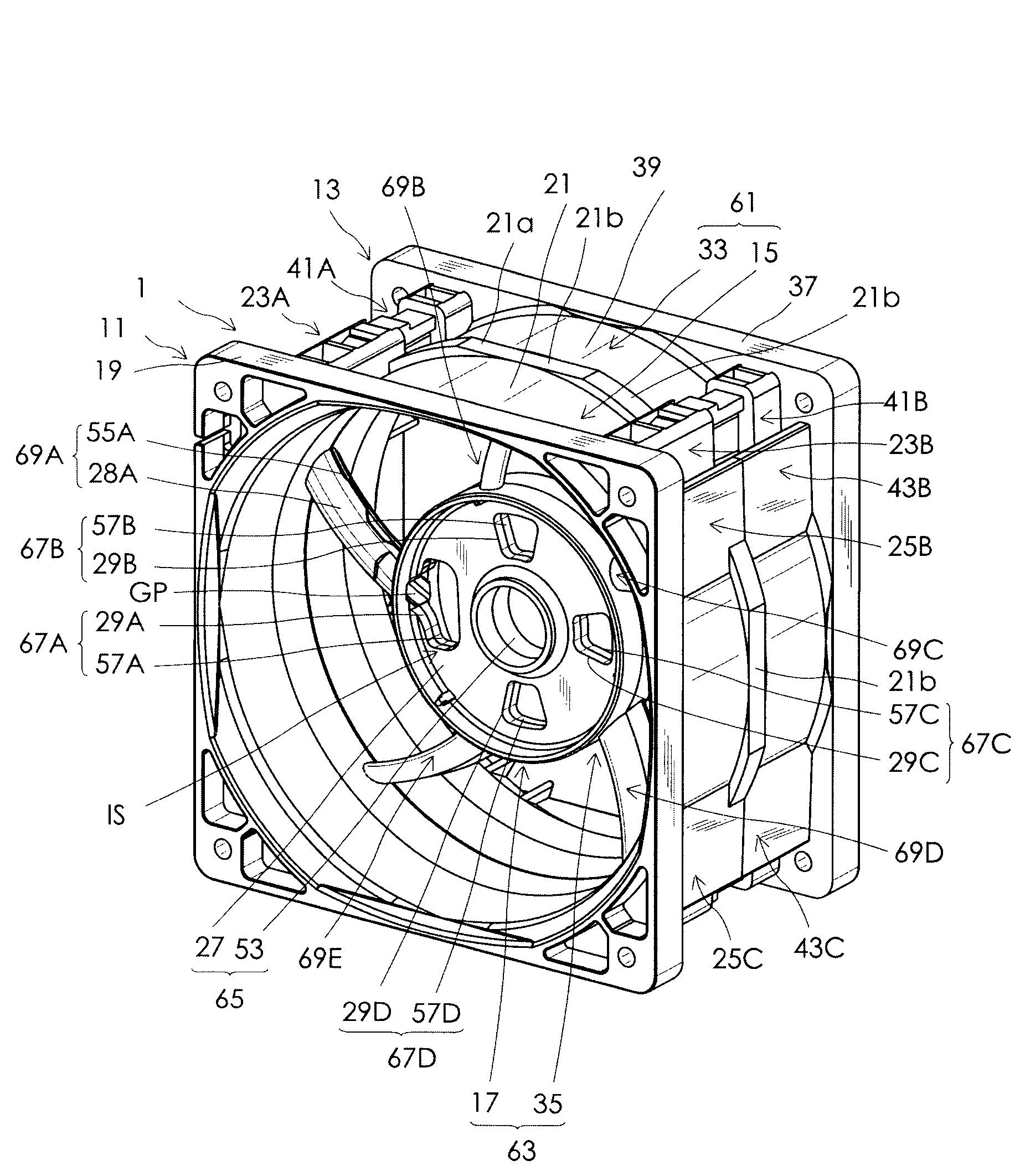
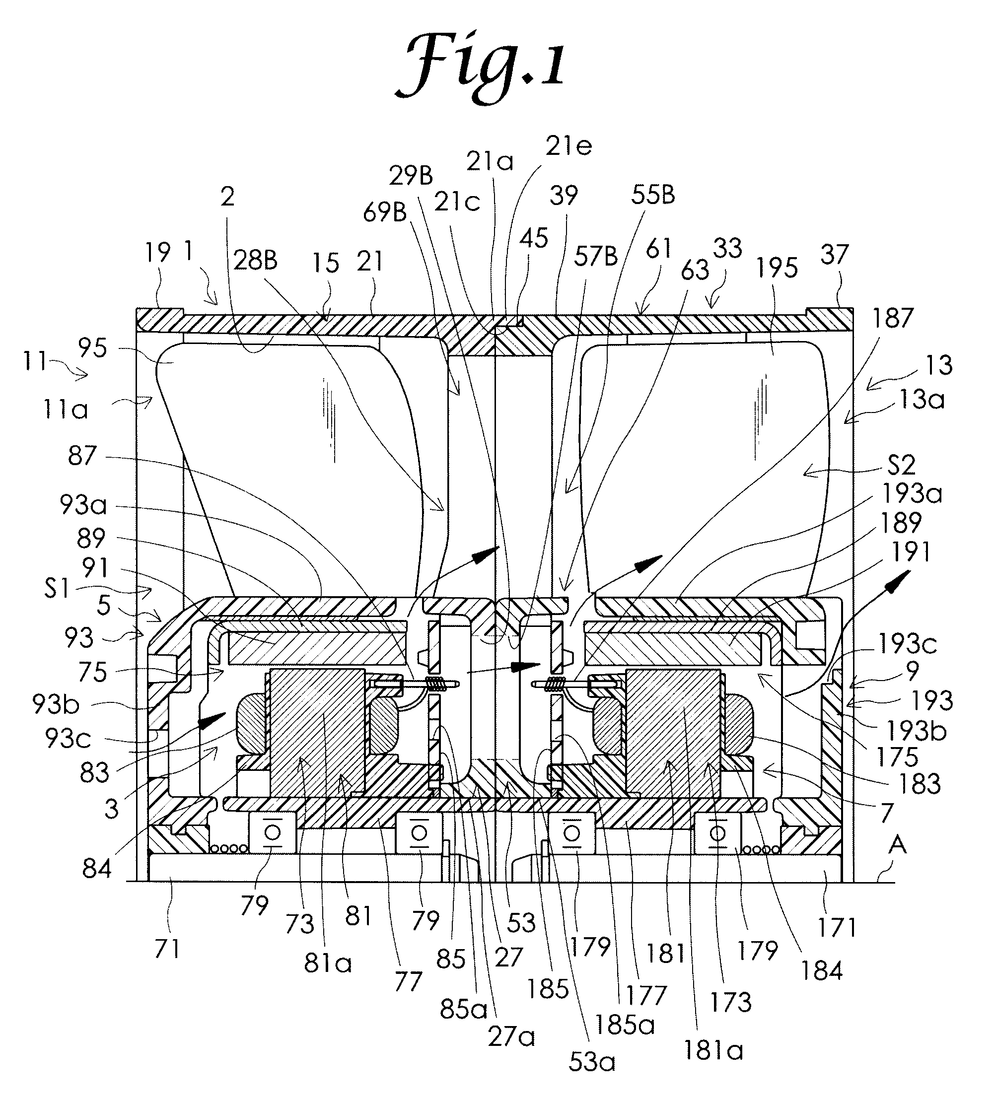
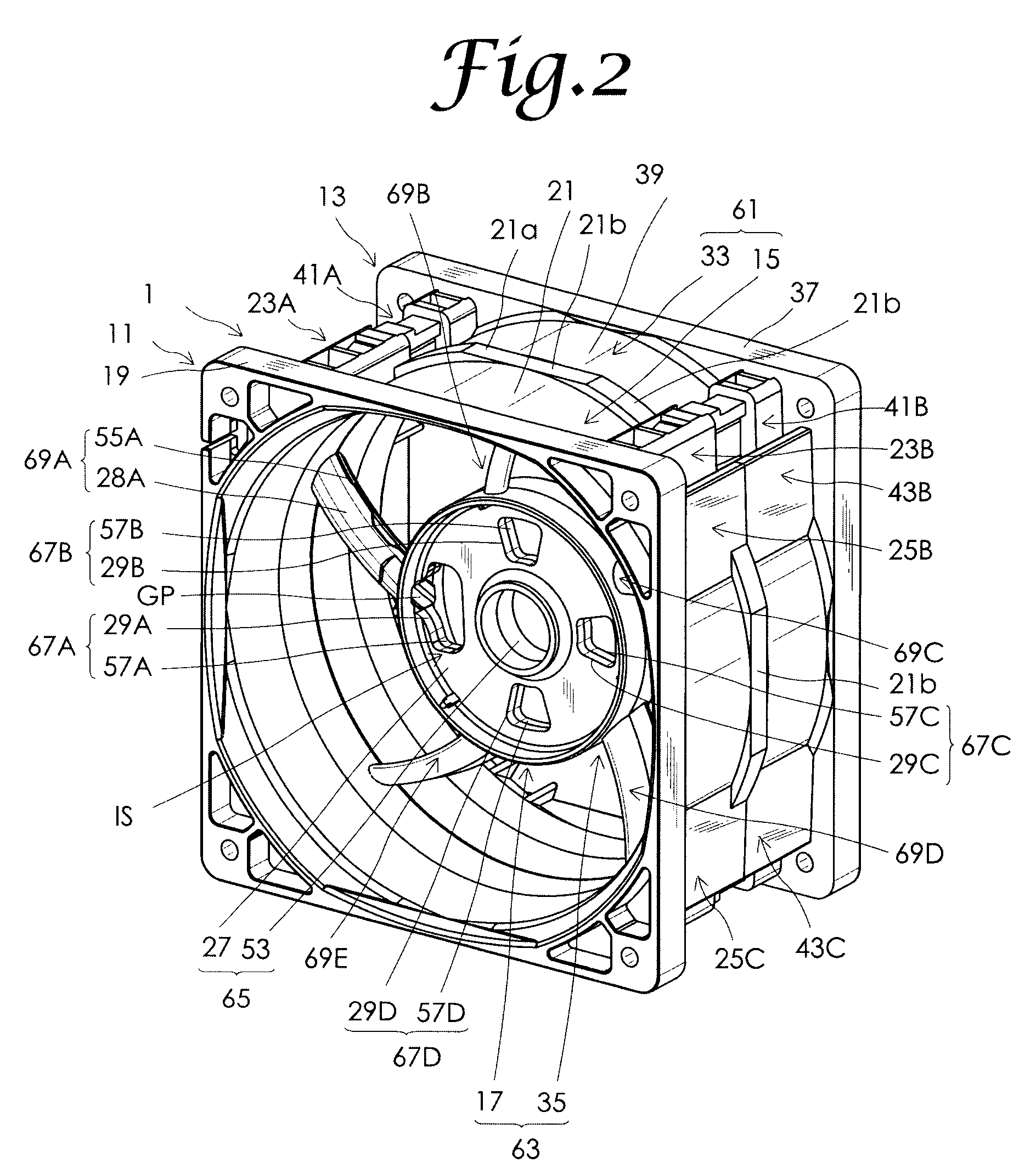
[0031]Now, an embodiment of the present invention will be described in detail with reference to the accompanying drawings. FIG. 1 is a cross-sectional view showing a half portion of a counter-rotating axial-flow fan in the embodiment of the present invention. As shown in FIG. 1, the counter-rotating axial-flow fan in this embodiment includes a housing 1, a first motor 3, a first impeller 5, a second motor 7, and a second impeller 9. The housing 1 comprises a housing body 61 including an air channel 2, a motor support frame 6 disposed in a central portion of the air channel 2. Further, as shown in FIGS. 2 to 6, the housing 1 is constituted from a first divided housing unit 11 and a second divided housing unit 13 that are coupled through a coupling structure. FIGS. 2 to 4 are a perspective view of the housing 1, a plan view of the housing 1, and a left side view of the housing 1, respectively. FIG. 5 is a partial cross-sectional view as taken along line V-V in FIG. 3. FIG. 6 is a cros...


PUM


Abstract

A counter-rotating axial-flow fan includes a housing that is constituted from a first divided housing unit and a second divided housing unit. Engaging members and first stopper portions are integrally formed with a first flange portion of the first divided housing unit. The first stopper portions are arranged adjacent to the engaging members. Engaged members and second stopper portions are integrally formed with a second flange portion of the second divided housing unit. The second stopper portions are arranged adjacent to the engaged members. The second stopper portions have leading ends that are abutted onto leading ends of the first stopper portions when the engaging members are completely engaged with the engaged members. Thus, damage of the first and second divided housing units is prevented when the first and second divided housing units are coupled.

Description

BACKGROUND OF THE INVENTION[0001]The present invention relates to a counter-rotating axial-flow fan used for cooling the inside of an electric appliance or the like.[0002]Japanese Patent No. 3904595 (Patent Document 1) discloses a counter-rotating axial-flow fan including a housing, which includes a housing body and a motor support frame. The housing body includes an air channel having a suction opening on one side in an axial line direction and a discharge opening on the other side in the axial line direction. The motor support frame is disposed in the central portion of the air channel. In this counter-rotating axial-flow fan, a first impeller that is rotated by a first motor is disposed within a first space that is defined between the motor support frame in the housing and the suction opening. Further, a second impeller that is rotated by a second motor is disposed within a second space that is defined between the motor support frame in the housing and the discharge opening. The ...

Claims


Application Information

Patent Timeline
Patent Type & Authority Applications(United States)
IPC IPC(8): F04D29/38
CPCF04D19/007F04D19/024F04D29/646F04D29/4226F04D25/0613F04D29/522
Inventor NISHIZAWA, TOSHIYAMARUYAMA, YASUHIROMURAYAMA, HAYATO
Owner SANYO DENKI CO LTD
Why Eureka
Try Eureka