Nozzle Tip for High Melt Pressure Applications

Inactive Publication Date: 2008-10-23
HUSKY INJECTION MOLDING SYST LTD
View PDF1 Cites 12 Cited by
  • Summary
  • Abstract
  • Description
  • Claims
  • Application Information

AI Technical Summary

Benefits of technology

[0008]One aspect of the present invention is to provide an improved injection nozzle suitable

Problems solved by technology

Such materials generally have relatively poor strength characteristics.
A significant drawback of these designs is the fact that highly conductive, low strength inner portion forms the sealing face between the nozzle tip and the nozzle housing in which the tip is mounted.
This arrangement leads to the inner portion being directly exposed

Method used


Image

  • Nozzle Tip for High Melt Pressure Applications
  • Nozzle Tip for High Melt Pressure Applications
  • Nozzle Tip for High Melt Pressure Applications

Examples


Embodiment Construction

[0022]In the following detailed description, numerous specific details are set forth in order to provide a thorough understanding of the invention. However, it will be understood by those skilled in the art that the present invention may be practiced without these specific details. For example, well-known methods, procedures, and components have not been described in detail so as not to obscure the present invention.

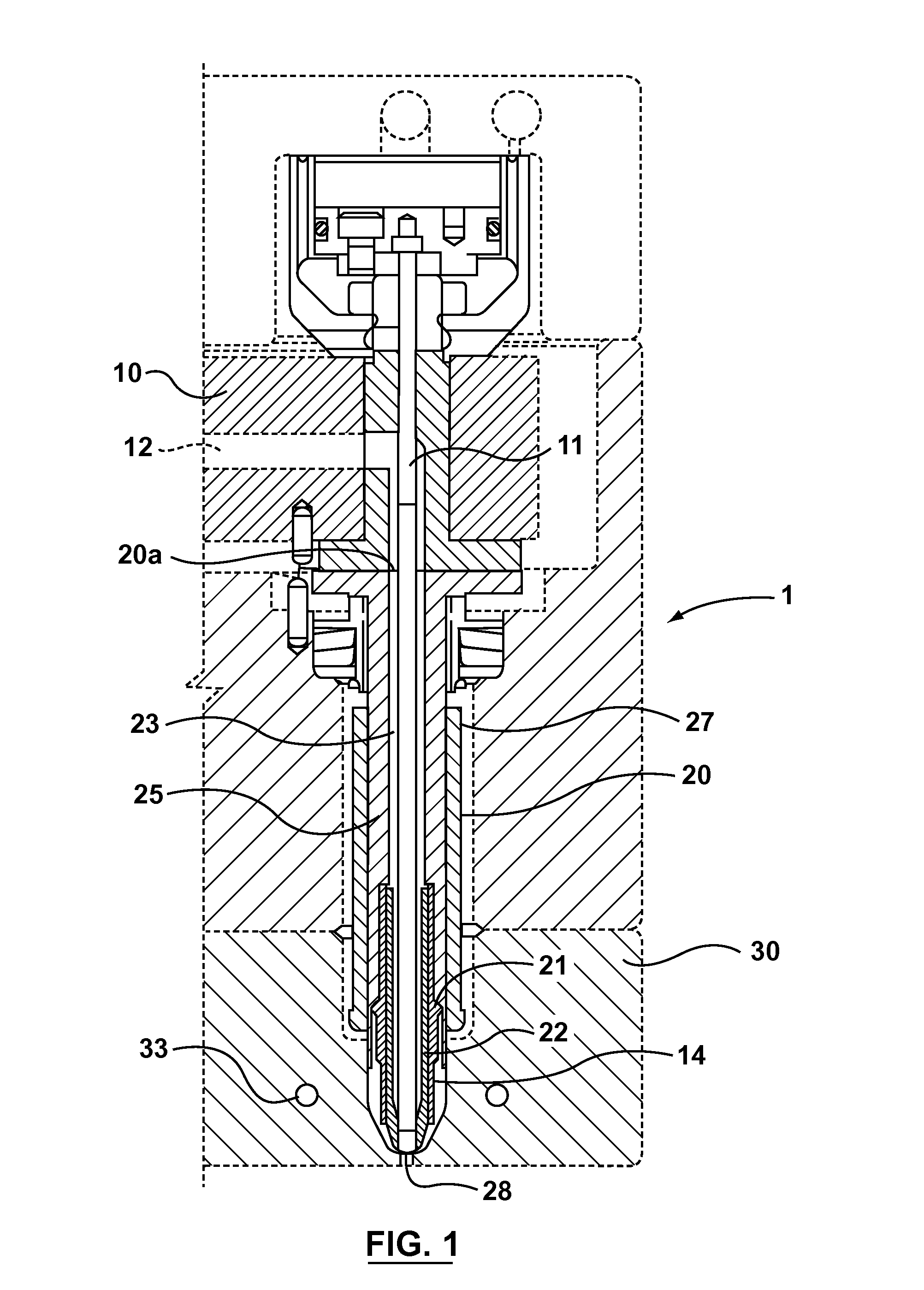
[0023]FIG. 1 illustrates the overall arrangement of an injection molding device 1. The device includes a mold manifold 10, having manifold melt channel 12 through which molten material reaches injection nozzle 20. While FIG. 1 shows valve stem 11 for regulating the flow of material through the melt channel, it should be noted that embodiments of the current invention may be used with any nozzle configuration including known thermal gating designs. In most applications several nozzles similar to nozzle 20 communicate with a plurality of melt channels 12 to improve product...


PUM

PropertyMeasurementUnit
Temperatureaaaaaaaaaa
Forceaaaaaaaaaa
Areaaaaaaaaaaa

Abstract

An improved nozzle for high melt pressure applications includes an inner body portion having a melt channel, the inner body portion having an inlet face and a melt outlet; an outer body portion having a seal face, with the outer body portion inducing a compressive force on the inner body portion at least during operation of the nozzle; the plane of the inlet face of the inner body portion intersecting the outer body portion, resulting in no part of the inner body portion extending beyond the seal face of the outer body portion; and the inner and outer body portions having different relative thermal conduction and expansion coefficients.

Description

CROSS REFERENCES[0001]None.TECHNICAL FIELD OF THE INVENTION[0002]The present invention relates generally to the field of injection molding equipment and, more particularly, to an improved high melt pressure nozzle tip.BACKGROUND OF THE INVENTION[0003]“Thin-walled” nozzle tips are desired for use in injection molding applications due to their small size, which allows the use of multiple nozzle tips within a single mold, for example, in high cavitation applications. In order to provide the material properties required for these applications, thin-walled nozzle tips are typically formed from concentric portions composed of different materials. The inner portion, which contains the channel through which molten material is delivered to the mold, must be made from a highly thermal conductive material. Such materials generally have relatively poor strength characteristics. To protect the low strength inner portion, the outer portion is preferably manufactured from a significantly higher st...

Claims


Application Information

Patent Timeline
IPC IPC(8): B29C45/00
CPCB29C45/278
Inventor JENKO, EDWARD JOSEPHMOHAMMED, SOHAIL
Owner HUSKY INJECTION MOLDING SYST LTD
Why Eureka
Try Eureka