
Agricultural working machine

a technology of working machine and agricultural machinery, which is applied in the direction of cutters, mowers, threshers, etc., can solve the problems of material jamming, abrupt increase in the amount of energy required for fragmentation and in the load of the fragmentation device, and achieve the effect of moderate load and moderate energy demand

Inactive Publication Date: 2008-10-23
CLAAS SELBSTFAHRENDE ERNTEMASCHINEN GMBH
View PDF22 Cites 4 Cited by
  • Summary
  • Abstract
  • Description
  • Claims
  • Application Information

AI Technical Summary

Benefits of technology

[0006]The object of the present invention, therefore, is to avoid the disadvantages of the related art and, in particular, to provide a conditioning device with which an intended influence on the fragmentation effect may be attained with a moderate energy demand and with moderate loads acting on the conditioning device.

Problems solved by technology

Given that the gap width of the passage is always constant, a design of this type has the problem, in particular, that, at high rates of crop material throughput, material may become jammed in the first passage, since the quantity of crop material that may be conveyed through the constant passage is limited.
In addition, at high rates of crop material throughput, there is an abrupt increase in the amount of energy required for fragmentation and in the loads on the fragmentation devices.
Given that, with a design of this type, the change in the passage depends exclusively on the ratio of forces being applied by the crop material throughput on the conditioning rollers and the counterforce of the energy-storing device, it is not possible to fragmentize the crop material to the full extent.

Method used


Image

  • Agricultural working machine
  • Agricultural working machine
  • Agricultural working machine

Examples


Embodiment Construction

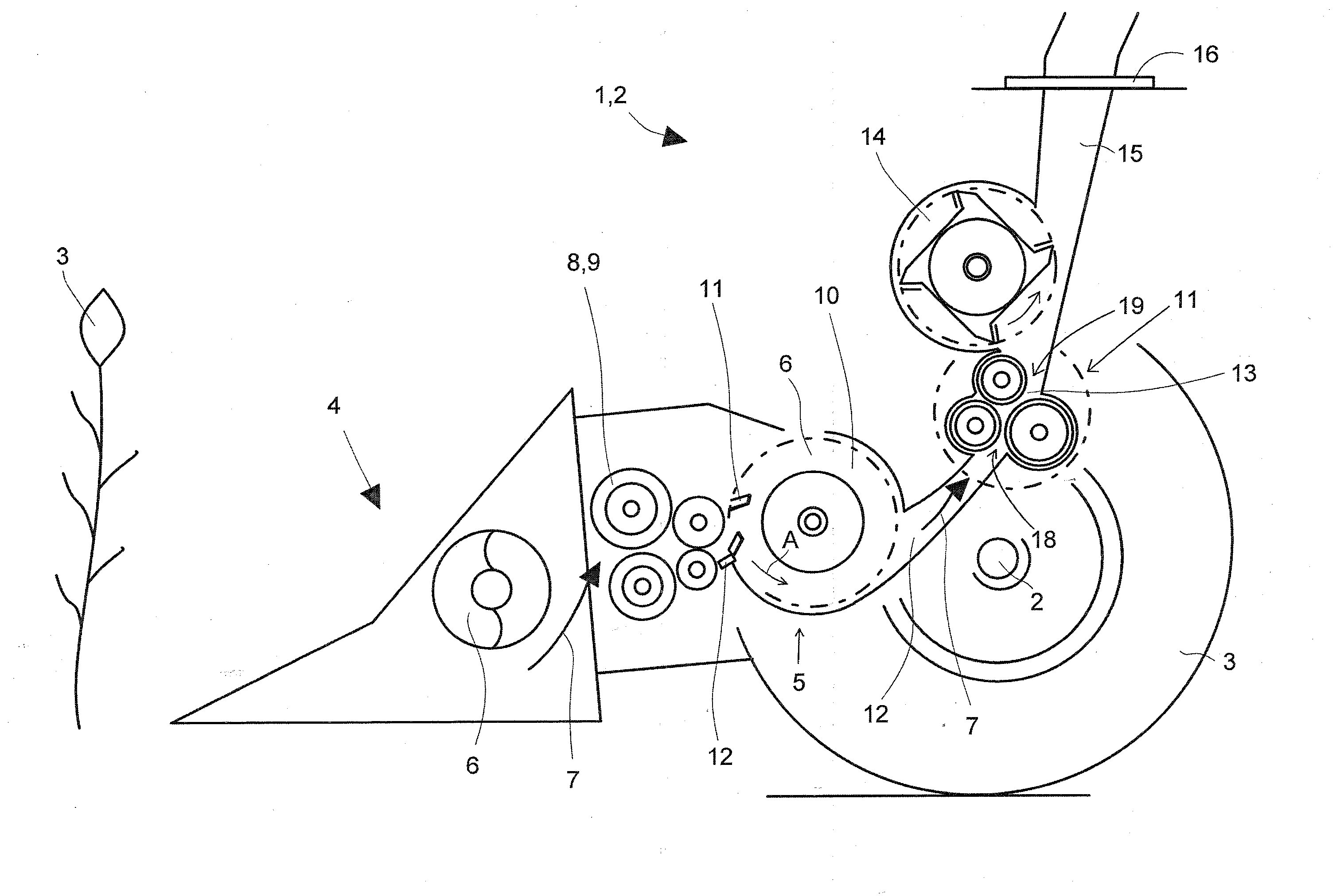
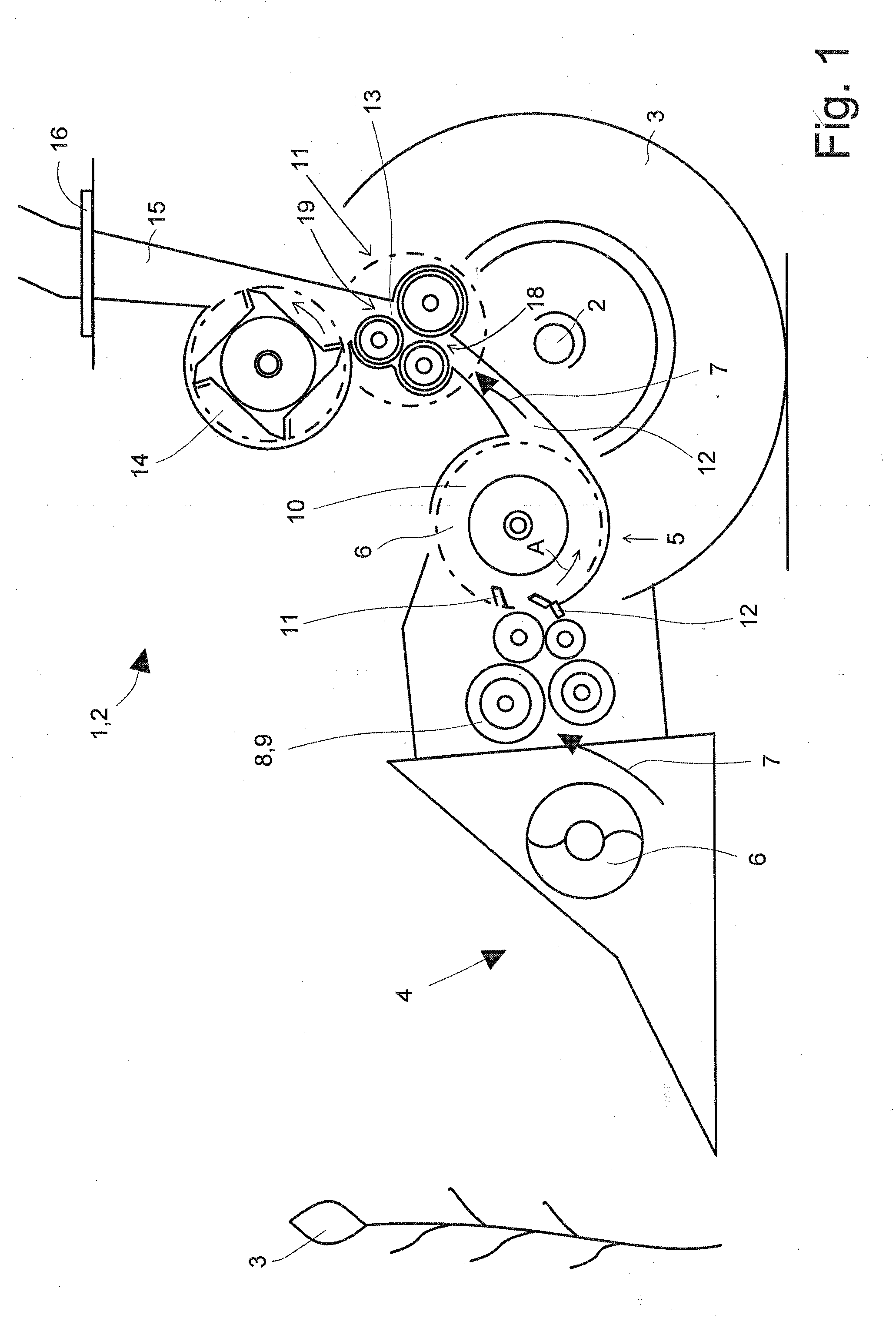
[0024]FIG. 1 shows an agricultural working machine 1 designed as self-propelled forage harvester 2, to the front region of which a front attachment 4—which is known per se and will therefore not be discussed in greater detail—is assigned, in order to pick up crop material 3. In a manner known per se, crop material 3 that has been picked up may be combined into a crop material flow 7 using at least one cross auger component and transferred to intake conveyor mechanisms 9—which are provided in pairs and are designed as intake and compression rollers 8—which compress crop material flow 7 and transfer it in their rear region to chopping assembly 10.

[0025]Rotating blades 11 of chopping assembly 10—in cooperation with a stationary shear bar 12—fragmentize crop material flow 7 and transfer it—in the rear region of chopping assembly 10—to an inventive conditioning device 13, which will be described in greater detail, e.g., a “corn cracker”. Conditioning device 13 transfers—in its rear regio...


PUM


Abstract

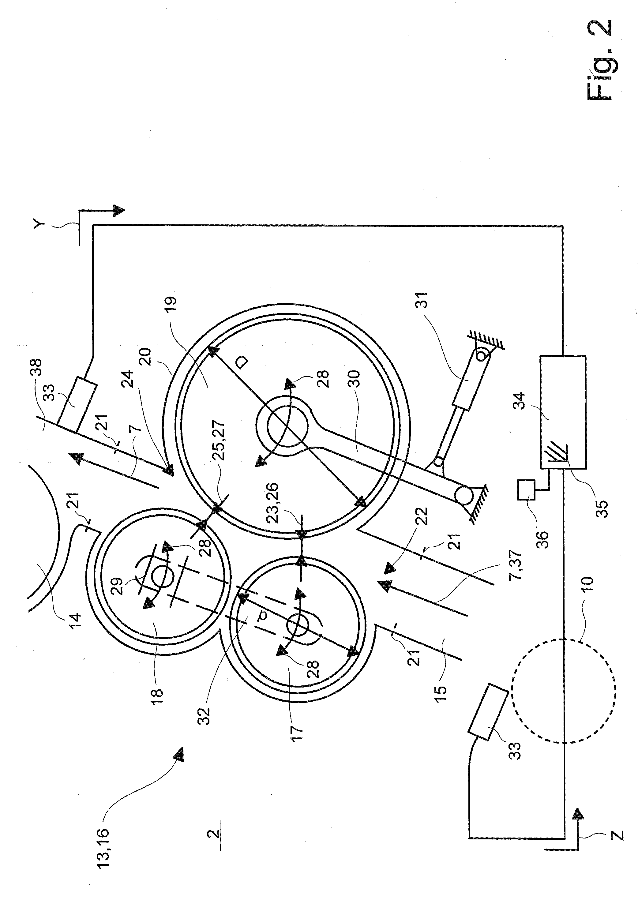
A forage harvester is provided with intake conveyor mechanisms, which convey the chopped material to a downstream chopping assembly, with an upper discharge chute located downstream of the chopping assembly, and with a conditioning device composed of a rotatably drivable roller assembly located between the chopping assembly and the upper discharge chute, and it is possible to adjust the at least two crop material passages between the conditioning rollers of the conditioning device and the gap width of the at least two passages in such a manner that the gap width of the passage located in the inlet region of the conditioning device is larger than the gap width of a passage located downstream in the material flow direction.

Description

CROSS-REFERENCE TO A RELATED APPLICATION[0001]The invention described and claimed hereinbelow is also described in German Patent Application DE 10 2007 018 885.6 filed on Apr. 19, 2007. This German Patent Application, subject matter of which is incorporated herein by reference, provides the basis for a claim of priority of invention under 35 U.S.C. 119(a)-(d).BACKGROUND OF THE INVENTION[0002]The present invention relates to a forage harvester, the intake conveyor mechanisms of which convey the crop material to a chopping assembly. A conditioning device that has at least two material passages is located downstream of the chopping assembly.[0003]Publication DE 195 49 504 makes known a generic forage harvester, the chopping assembly of which is located downstream of a conditioning device that includes three post-fragmentation rollers. The post-fragmentation rollers are positioned relative to each other such that at least two material passages are formed between their circumferential su...

Claims


Application Information

Patent Timeline
IPC IPC(8): A01F12/40A01F29/09
CPCA01D43/10A01F29/12
Inventor POTTHAST, ARNE
Owner CLAAS SELBSTFAHRENDE ERNTEMASCHINEN GMBH
Learn More