
Method for Adaptive Complex Wavelet Based Filtering of Eeg Signals

a complex wavelet and filtering technology, applied in the field of extracting or denoising auditory brains, can solve the problems of not being unable to shift-invariant in most practical forms, and distortion or obscuration of slow negative waves in the 10 ms region

Inactive Publication Date: 2008-10-23
BRAINSCOPE SPV LLC
View PDF8 Cites 32 Cited by
  • Summary
  • Abstract
  • Description
  • Claims
  • Application Information

AI Technical Summary

Benefits of technology

"The present invention provides a method for adaptive filtering of EEG signals in the wavelet domain using a nearly shift-invariant complex wavelet transform. This method involves segmenting the EEG signal data into a set of trials, overlapping them with a number of frames, and computing a dual-tree complex wavelet transform for each trial. The phase variance of each resulting normalized wavelet coefficient is then computed, and the magnitude of each wavelet coefficient is selectively scaled according to the phase variance of the coefficients. The resulting wavelet coefficients are then utilized to reconstruct the ABR signal extracted from the EEG data. This method allows for improved accuracy and reliability in the analysis of EEG signals."

Problems solved by technology

However, auditory evoked potential signals are typically one order of magnitude smaller than the EEG signals, and are therefore not directly visible from a raw EEG signal trace.
However, it is know that selecting a high-pass frequency of 100 Hz or more, which is commonly used in ABR analysis, may distort or obscure the slow negative wave in the 10 ms region.
However, when the desired signal is buried in high energy noise, i.e. with and SNR of less than 0 dB, as is often the case with ABR signals contained in a high-energy EEG signal, it has been shown that conventional wavelet denoising fails.
An additional drawback of classical DWT is that it is not shift-invariant in most practical forms.
One exception is the undecimated form of the dyadic wavelet decomposition tree, however the computational complexity and high redundancy of this form renders it unattractive for many signal processing applications.

Method used


Image

  • Method for Adaptive Complex Wavelet Based Filtering of Eeg Signals
  • Method for Adaptive Complex Wavelet Based Filtering of Eeg Signals
  • Method for Adaptive Complex Wavelet Based Filtering of Eeg Signals

Examples


Embodiment Construction

[0025]The following detailed description illustrates the invention by way of example and not by way of limitation. The description clearly enables one skilled in the art to make and use the invention, describes several embodiments, adaptations, variations, alternatives, and uses of the invention, including what is presently believed to be the best mode of carrying out the invention.

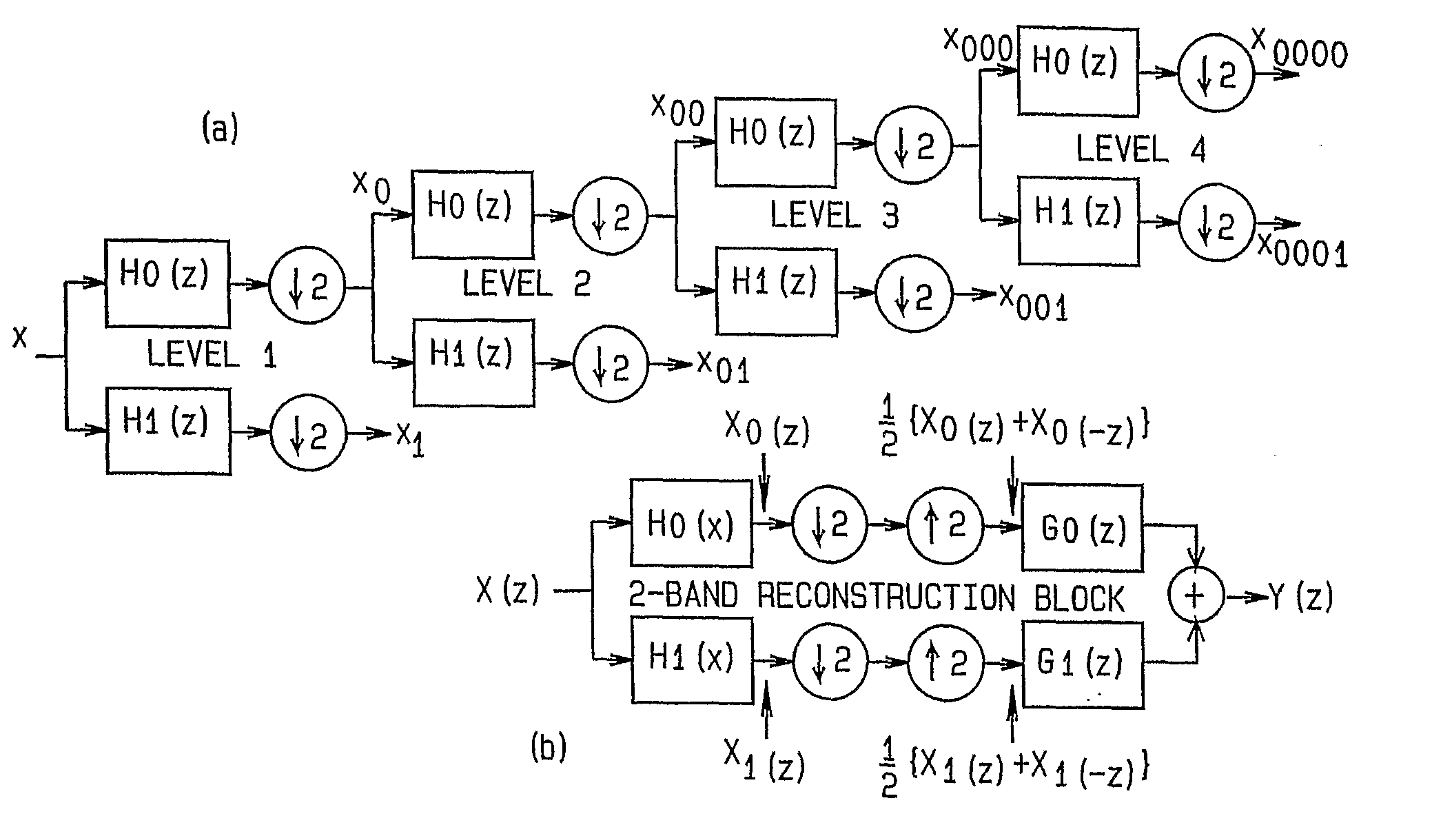
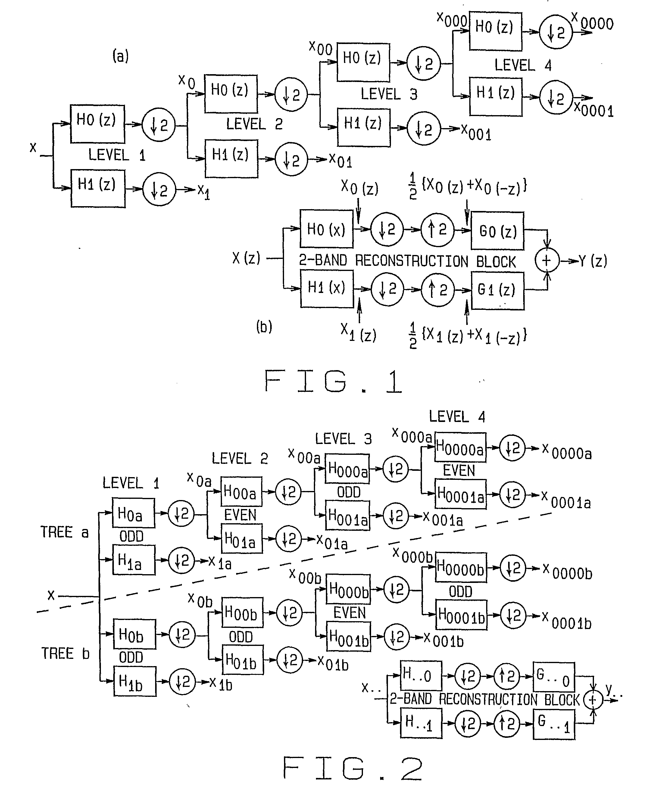
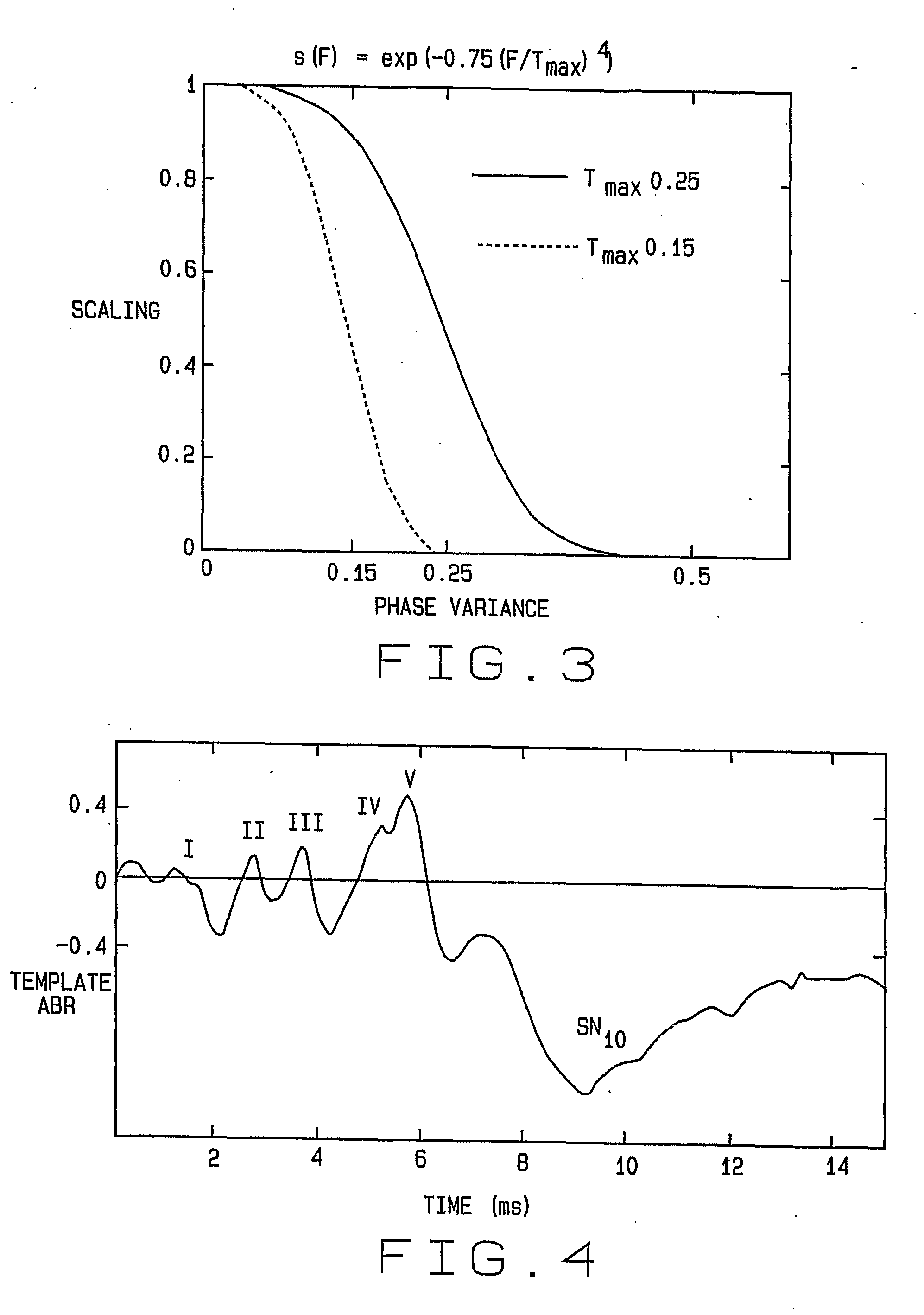
[0026]The Complex Wavelet Transform (CWT) overcomes the shift-invariance deficiencies of the classing discrete wavelet transform, and has been successfully utilized for video image denoising applications. A CWT is based on a structure of low-pass filters and high-pass filters, each having complex coefficients to generate complex output samples. FIG. 1 illustrates four levels of a complex wavelet tree for a real one dimensional input signal x. The real and imaginary parts (r and j) of the inputs and outputs are shown separately. The energy of each CWT band is approximately constant at all levels, and is sh...


PUM


Abstract

A method for adaptive filtering of EEG signals in the wavelet domain using a nearly shift-invariant complex wavelet transform. EEG signal data is segmented into a set of K “trials” or “light averages” of M-frames of data each. These trials are overlapped by a number of frames P, where P<M. A dual-tree complex wavelet transform is computed for each light average K of EEG signal data. Next, the phase variance of each resulting normalized wavelet coefficient is computed, and the magnitude of each wavelet coefficient is selectively scaled according to the phase variance of the coefficients. The resulting wavelet coefficients are then utilized to reconstruct the ABR signal extracted from the EEG data.

Description

TECHNICAL FIELD[0001]The present invention relates generally to the extraction or denoising of auditory brainstem responses (ABR) from an electroencephalogram (EEG) signal, and in particular, to a method for adaptive filtering of EEG signals in the wavelet domain using a nearly shift-invariant complex wavelet transform.BACKGROUND ART[0002]Auditory evoked potential (AEP) signals are transient electrical biosignals produced by various regions of the human brain in response to auditory stimuli, such as a repetition of “clicks”. These signals are traditionally categorized into three groups. The first group is commonly referred to as the auditory brainstem response (ABR), and occurs during the first 11 ms following the stimulus. The second group is the mid-latency cortical response (MLR), also known as the mid-latency evoked potential (ML-EP), which is typically confined to the next 70 ms. The final group is the slow cortical response, which begins to occur at about 80 ms following the s...

Claims


Application Information

Patent Timeline
Patent Type & Authority Applications(United States)
IPC IPC(8): A61B5/0476
CPCA61B5/04017A61B5/0484A61B5/7203A61B5/725A61B5/7257A61B5/726G06K9/00516A61B5/316A61B5/377G06F2218/06A61B5/374
Inventor CAUSEVIC, ELVIR
Owner BRAINSCOPE SPV LLC
Learn More