Methods for displaying physical network topology and environmental status by location, organization, or responsible party

a network topology and environmental status technology, applied in the field of system and method of monitoring network equipment, can solve the problems of equipment deterioration, inability to maintain a constant state of physical network topology, and inability to tolerate excess heat, dust or humidity in modern computer systems,

Active Publication Date: 2008-10-23
AMERICA POWER CONVERSION CORP
View PDF76 Cites 112 Cited by
  • Summary
  • Abstract
  • Description
  • Claims
  • Application Information

AI Technical Summary

Problems solved by technology

Keeping track of numerous computers, along with associated bridges, routers, backup power supplies, etc., can be a formidable task.
While reliable, modern computer systems cannot tolerate excess heat, dust or humidity.
Heat can rapidly cause equipment deterioration.
Failure of cooling fans can reduce equipment lifetime to days or hours.
A single high-speed LAN (local area network) failure can cause slow system response.
These and other such failures within the equipment in a server room occur routinely and can cause great disruption to a business.
However, all of these solutions are expensive to implement, complex, and difficult to maintain and train personnel to use them.
As a result, small to medium companies having small to medium networks are left in the position of requiring a means to monitor and maintain their computer network equipment from failing while not having the resources to afford the high-priced solutions.
Many firms cannot afford a high-end solution or simply do not have the time and resources to train their IT personnel to learn and use complex systems.
This is especially true for companies having multiple server rooms and that have concerns about routine access to each of these rooms.
Additionally, concerns exist with current solutions regarding the manpower intensiveness of these solutions.
Most network monitoring solutions can consume a full or part-time employee.
The financial justification for these systems is, therefore, difficult because network equipment typically fails yearly or on a disaster basis, and the cost of recovery is seen as less than that of maintaining a full-time employee to routinely monitor the equipment.
Typical problems include localized environmental excesses leading to failure.
Another problem is theft.
Typical monitoring solutions do not provide for video imaging of remote server locations over a network.
A server room's environment requires monitoring because out-of-limit environmental variables can eventually affect the equipment in the room.
For example, high temperatures, humidity (for example, from water leaks), or lack of airflow can detrimentally affect the equipment.
While the expense of replacing server room components if they fail is great, currently existing monitoring solutions are not cost effective for smaller-sized companies to implement despite the potential costs of such losses.
While these mechanisms can be quite effective, they introduce additional costs, through additional software, hardware, configuration, administration, and network bandwidth.
Beyond the application to server rooms and rack mountings of network equipment, various other monitoring systems suffer from the same failures and deficiencies associated with information accessibility, organization, and presentation.
As such, many typical network monitoring systems suffer from deficiencies in information accessibility, organization, and presentation.

Method used


Image

  • Methods for displaying physical network topology and environmental status by location, organization, or responsible party
  • Methods for displaying physical network topology and environmental status by location, organization, or responsible party
  • Methods for displaying physical network topology and environmental status by location, organization, or responsible party

Examples


Embodiment Construction

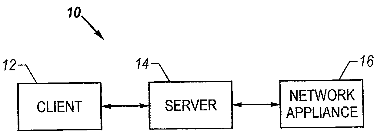
[0055]FIG. 1 is a schematic block diagram of the system according to the invention. The system 10 has a server, a client 12 and a network appliance 16. The server 14 is connected to one or more network appliances 16 through an interconnected network. The server 14 may function to transfer sensor data from the network appliance 16 and transfer configuration data to the network appliances 16. The server 14 is also connected to a client machine 12. The client machine 12 may access, display and / or manipulate data stored on the server 14. In this manner, the client 12 may remotely monitor network appliances 16 and the client 12 may reconfigure the network appliances 16.

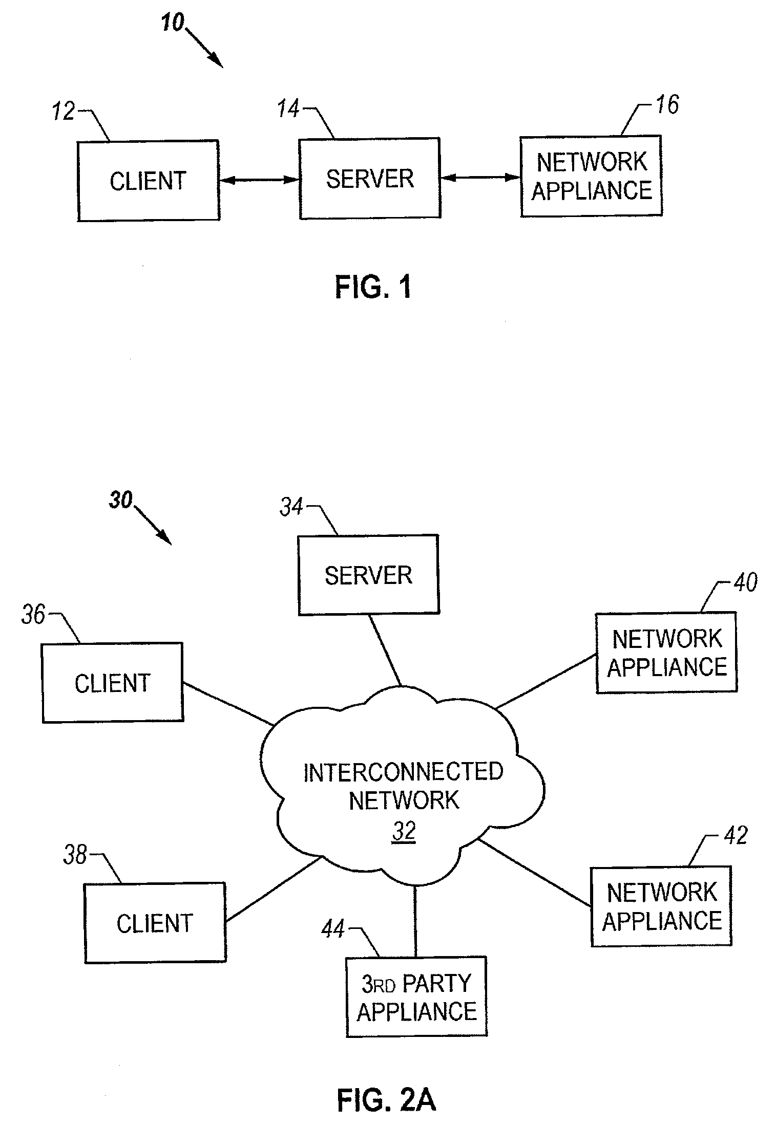
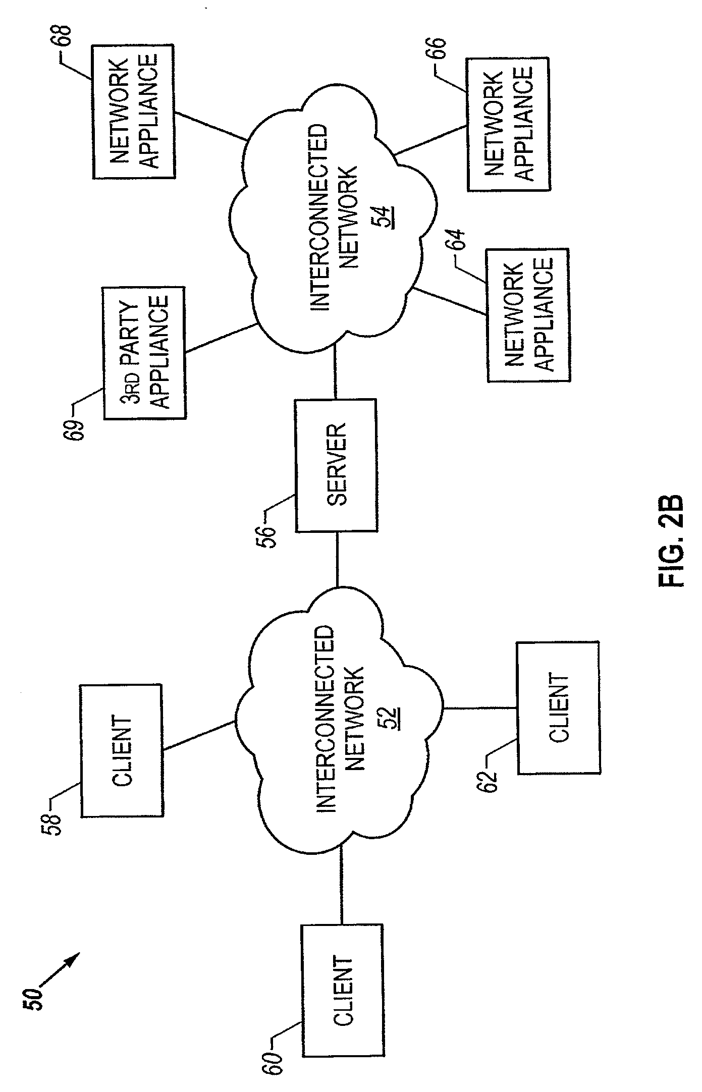
[0056]The client 12 may be connected to the server 14 through an interconnected network. Further, the server 14 may be connected to the network appliance 16 through an interconnected network. The interconnected network may take various forms. These forms may include a global network, wide area network, local area network, ...


PUM


Abstract

The invention is directed to a system for remote monitoring of a space and equipment. The space and equipment may, for example, be a sever room and associated network equipment. The system has network appliances, a server, and a client machine. The server receives data from a network appliance. The server may then deliver an application and data to the client machine for viewing and manipulating the data. The client machine may display the data as a mapping, displaying icons associated with the network appliances. The client machine may also graph the data. Further, the client machine may manipulate the organization of the data, the configuration settings of the network appliances, and store map and graph configurations.

Description

RELATED APPLICATIONS[0001]This application is a continuation-in-part of U.S. patent application Ser. No. 09 / 429,504, filed Oct. 27, 1999 entitled: “METHOD AND SYSTEM FOR MONITORING COMPUTER NETWORKS AND EQUIPMENT”, and is incorporated herein by reference in its entirety.[0002]This application is a continuation-in-part of U.S. patent application Ser. No. 10 / 057,563, filed Jan. 25, 2002 entitled: “METHOD AND SYSTEM FOR A SET OF NETWORK APPLIANCES WHICH CAN BE CONNECTED TO PROVIDE ENHANCED COLLABORATION, SCALABILITY, AND RELIABILITY”, which claims priority of U.S. provisional Application No. 60 / 264,445, filed Jan. 26, 2001 entitled: “METHOD AND SYSTEM FOR A SET OF NETWORK APPLIANCES WHICH CAN BE CONNECTED TO PROVIDE ENHANCED COLLABORATION, SCALABILITY, AND RELIABILITY and is incorporated herein by reference in its entirety.[0003]This application claims priority of U.S. provisional Application, No. 60 / 279,059, filed Mar. 27, 2001 entitled: “SENSOR PLAYBACK SYSTEM AND METHOD”, and is inc...

Claims


Application Information

Patent Timeline
Patent Type & Authority Applications(United States)
IPC IPC(8): G06F15/16G06F15/173
CPCH04L41/0853H04L41/0856H04L67/12H04L67/42H04L67/025H04L43/0817H04L67/01
Inventor CHILDERS, SLOAN K.ELDERTON, JOHNPRIMM, MICHAEL
Owner AMERICA POWER CONVERSION CORP
Why Eureka
Try Eureka