
Fastening mechanism

a technology of fastening mechanism and electronic device, which is applied in the field of fastening mechanism, can solve the problems of user difficulty in assembling a computer, inconvenient and time-consuming, etc., and achieve the effect of fast, time-saving assembly and disassembly of an electronic devi

Inactive Publication Date: 2008-10-30
INVENTEC CORP
View PDF0 Cites 3 Cited by
  • Summary
  • Abstract
  • Description
  • Claims
  • Application Information

AI Technical Summary

Benefits of technology

[0007]In order to achieve the above and other objectives, the present invention discloses a fastening mechanism for rapidly fastening accessories of an electronic device to the casing thereof and conveniently unfastening the accessories of the electronic device.
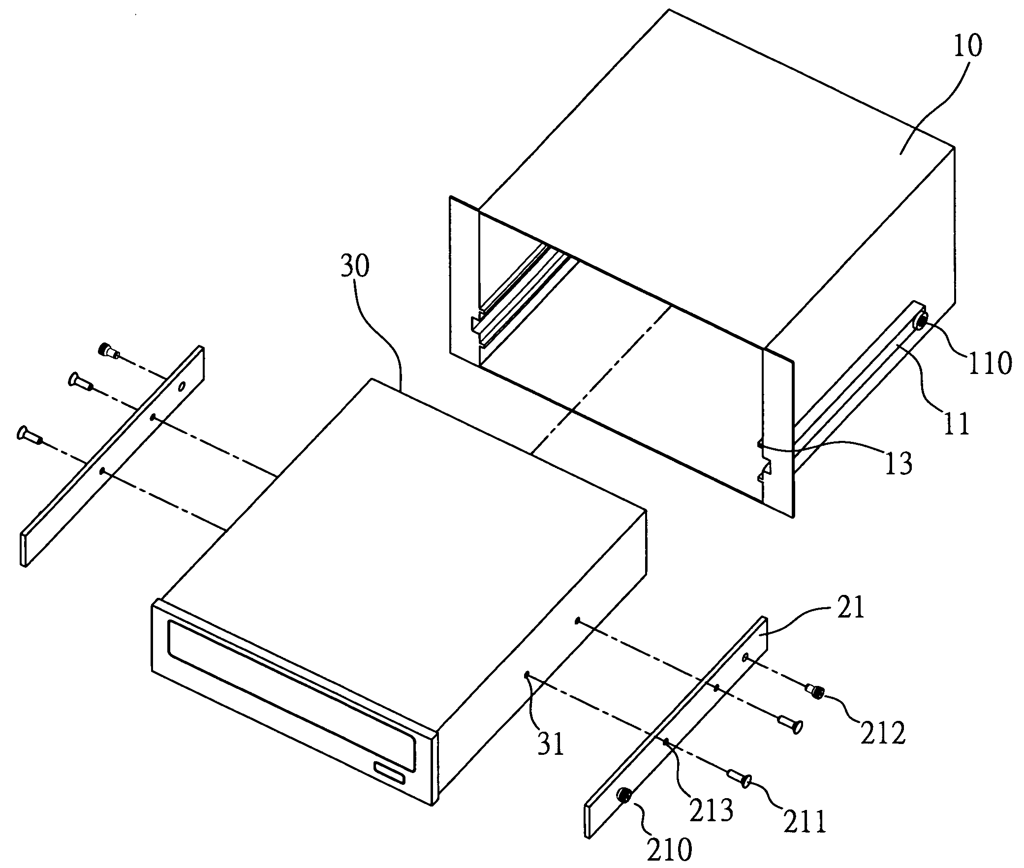
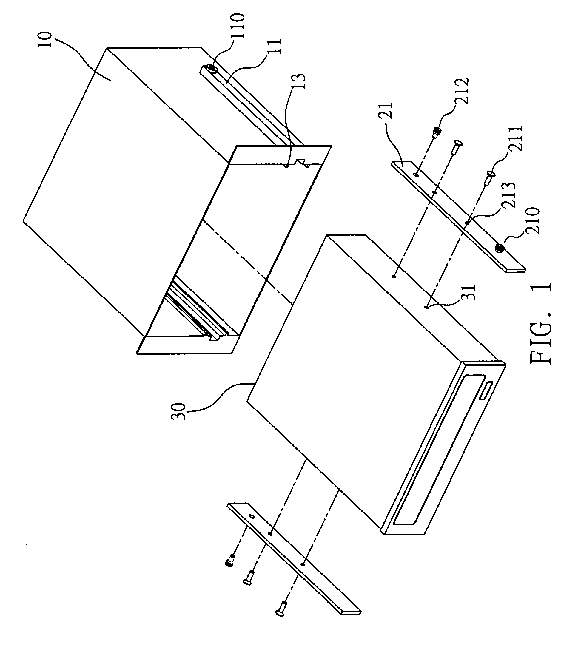
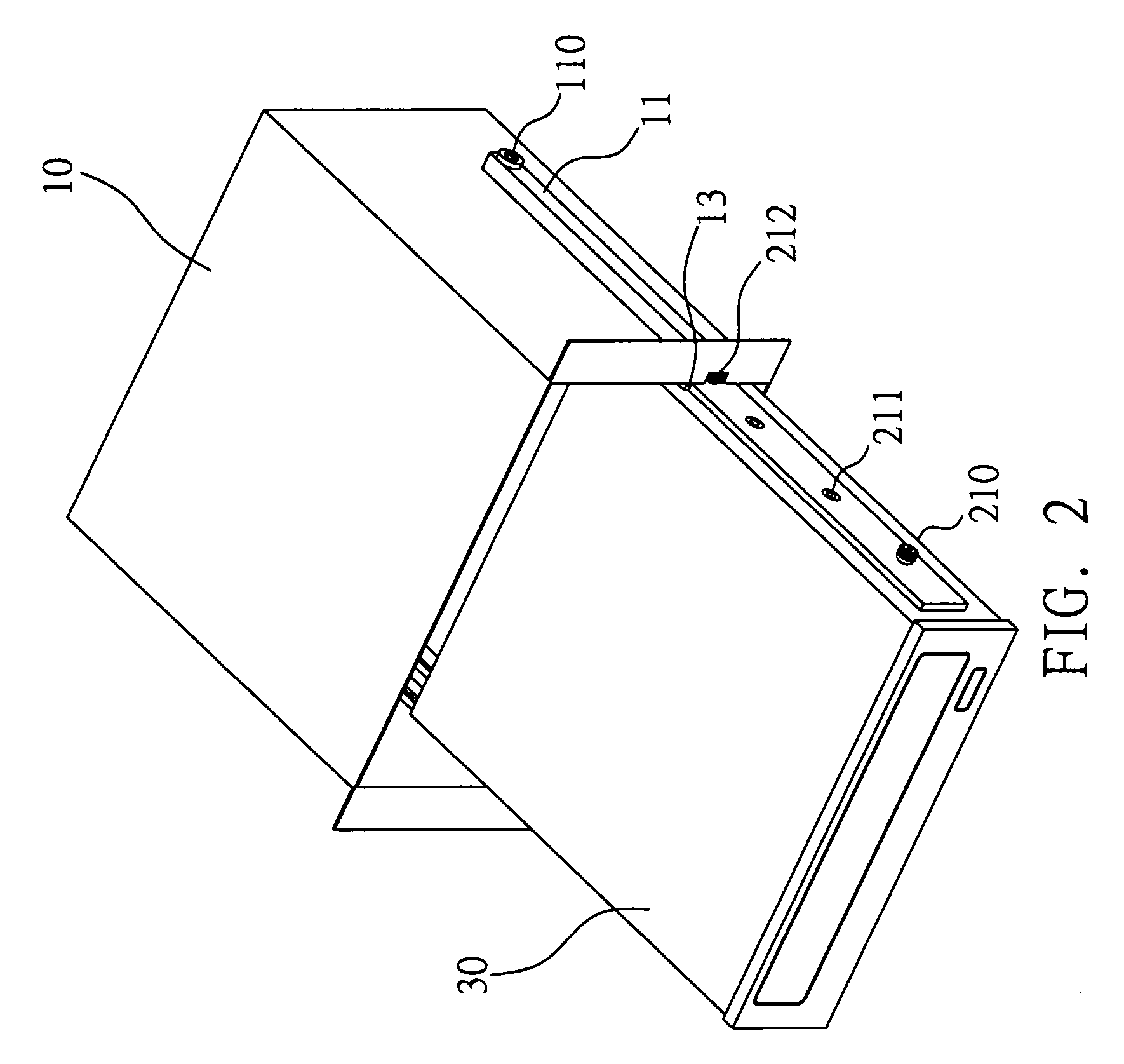
[0008]The fastening mechanism of the present invention comprises: a box with two side walls each provided with a first guiding groove extending from the front to the rear of the box and a second guiding groove corresponding in position to the first guiding groove, wherein at least one of the first guiding grooves is formed with a through-hole perpendicularly penetrating the related one of the two side walls of the box; two fastening elements matching the second guiding grooves and disposed on two side walls of the electronic device respectively; and two resilient positioning elements disposed on the two fastening elements respectively and corresponding in position to the through-hole of first guiding groove of the box, wherein at least one of the two resilient positioning elements corresponds in position to the through-hole of first guiding groove of the box and comprises a positioning portion; wherein the fastening mechanism allows users to render the resilient positioning element resiliently compressed by pressing on the positioning portion of resilient positioning element, and slidingly dispose the positioning portion of the resiliently compressed resilient positioning element in the first guiding groove by insertably engaging the fastening element to the second guiding groove of the box, such that the positioning portion is insertably engaged to the through-hole of first guiding groove under resilience of the resilient positioning element as soon as the positioning portion corresponds in position to the through-hole of first guiding groove, thus fastening the electronic device in the box.
[0010]Unlike the prior art that teaches fastening an electronic device to the casing thereof by means of a plurality of screws, the present invention has an advantage, that is, fast, time-saving assembly and disassembly of an electronic device.
[0011]Accordingly, the fastening mechanism of the present invention solves the drawbacks of the prior art and enables fast, time-saving assembly and disassembly of an electronic device.

Problems solved by technology

In the event that a user does not have any screwdriver or a similar tool at hand, the user will find it difficult to assemble a computer.
On the other hand, changing a hard disk drive or CD-ROM drive already fastened to the casing entails unscrewing the hard disk drive or CD-ROM drive with a screwdriver or a similar tool, which is rather inconvenient and time-consuming.
Accordingly, an issue calling for an urgent solution involves devising a fastening mechanism for solving the aforesaid drawbacks of the prior art.

Method used


Image

  • Fastening mechanism
  • Fastening mechanism
  • Fastening mechanism

Examples


Embodiment Construction

[0024]The following specific embodiments are provided to illustrate the present invention. Persons skilled in the art can readily gain insight into other advantages and features of the present invention based on the contents disclosed in this specification.

[0025]Points to note are as follows: all the accompanying drawings are simple schematic diagrams intended to schematically describe the basic structure of the present invention. Hence, in the drawings, only those components related to the present invention are shown, and the shown components are not drawn according to their actual quantity, shape and dimensions when implemented; in practice, the specifications, quantity, and dimensions of the components may be devised as appropriate, without being limited by the present invention.

[0026]FIGS. 1 and 2 are schematic views showing the first preferred embodiment of the fastening mechanism of the present invention. The first preferred embodiment of the fastening mechanism of the present...


PUM

PropertyMeasurementUnit
resilienceaaaaaaaaaa
resilient extensionaaaaaaaaaa
widthaaaaaaaaaa

Abstract

A fastening mechanism for use in an electronic device, including: a box with two side walls each provided with a first guiding groove formed with a through-hole and a second guiding groove; two fastening elements matching the second guiding grooves; and two resilient positioning elements disposed on the two fastening elements respectively and corresponding in position to the through-hole, wherein at least one of the two resilient positioning elements corresponds in position to the through-hole and includes a positioning portion. Users render the resilient positioning element resiliently compressed by pressing on the positioning portion of resilient positioning element, and slidingly dispose the positioning portion of the resiliently compressed resilient positioning element in the first guiding groove by insertably engaging the fastening element to the second guiding groove, such that the positioning portion is insertably engaged to the through-hole as soon as the positioning portion corresponds in position to the through-hole.

Description

BACKGROUND OF THE INVENTION[0001]1. Field of the Invention[0002]The present invention relates to fastening mechanisms, and more particularly, to a fastening mechanism for fastening an electronic device to a casing.[0003]2. Description of the Prior Art[0004]Electronic apparatus nowadays is assembled mainly by putting delicate components and devices inside the casing of the host. For instance, a computer is assembled by installing essential parts, such as a motherboard, hard disk drive, CD-ROM drive, and power supply, in the casing. A fixing means nowadays entails screwing, for example, a hard disk drive or CD-ROM drive, to the casing with a screwdriver or an equivalent thereof. In the event that a user does not have any screwdriver or a similar tool at hand, the user will find it difficult to assemble a computer. On the other hand, changing a hard disk drive or CD-ROM drive already fastened to the casing entails unscrewing the hard disk drive or CD-ROM drive with a screwdriver or a s...

Claims


Application Information

Patent Timeline
Patent Type & Authority Applications(United States)
IPC IPC(8): B29D5/00
CPCY10T29/49785G11B33/124
Inventor CHEN, YUNG-CHUNG
Owner INVENTEC CORP
Learn More