Engine-Driven Air Compressor/Generator Load Priority Control System and Method

a technology of priority control system and engine, which is applied in the direction of machines/engines, mechanical equipment, manufacturing tools, etc., can solve the problems of so as to achieve the effect of reducing the number of problems, reducing the efficiency of engine power supply, and increasing the number of problems

Active Publication Date: 2008-10-30
ILLINOIS TOOL WORKS INC
View PDF13 Cites 102 Cited by
  • Summary
  • Abstract
  • Description
  • Claims
  • Application Information

AI Technical Summary

Problems solved by technology

However, adding multiple devices to a welding system creates additional concerns.
For instance, an engine may produce a limited amount of power and, thus, the power desired to operate the multiple devices may exceed that amount of power that the engine can efficiently supply.
As a result, the loading of the engine may cause an overload condition, resulting in a decrease in system performance.

Method used


Image

  • Engine-Driven Air Compressor/Generator Load Priority Control System and Method
  • Engine-Driven Air Compressor/Generator Load Priority Control System and Method
  • Engine-Driven Air Compressor/Generator Load Priority Control System and Method

Examples


Embodiment Construction

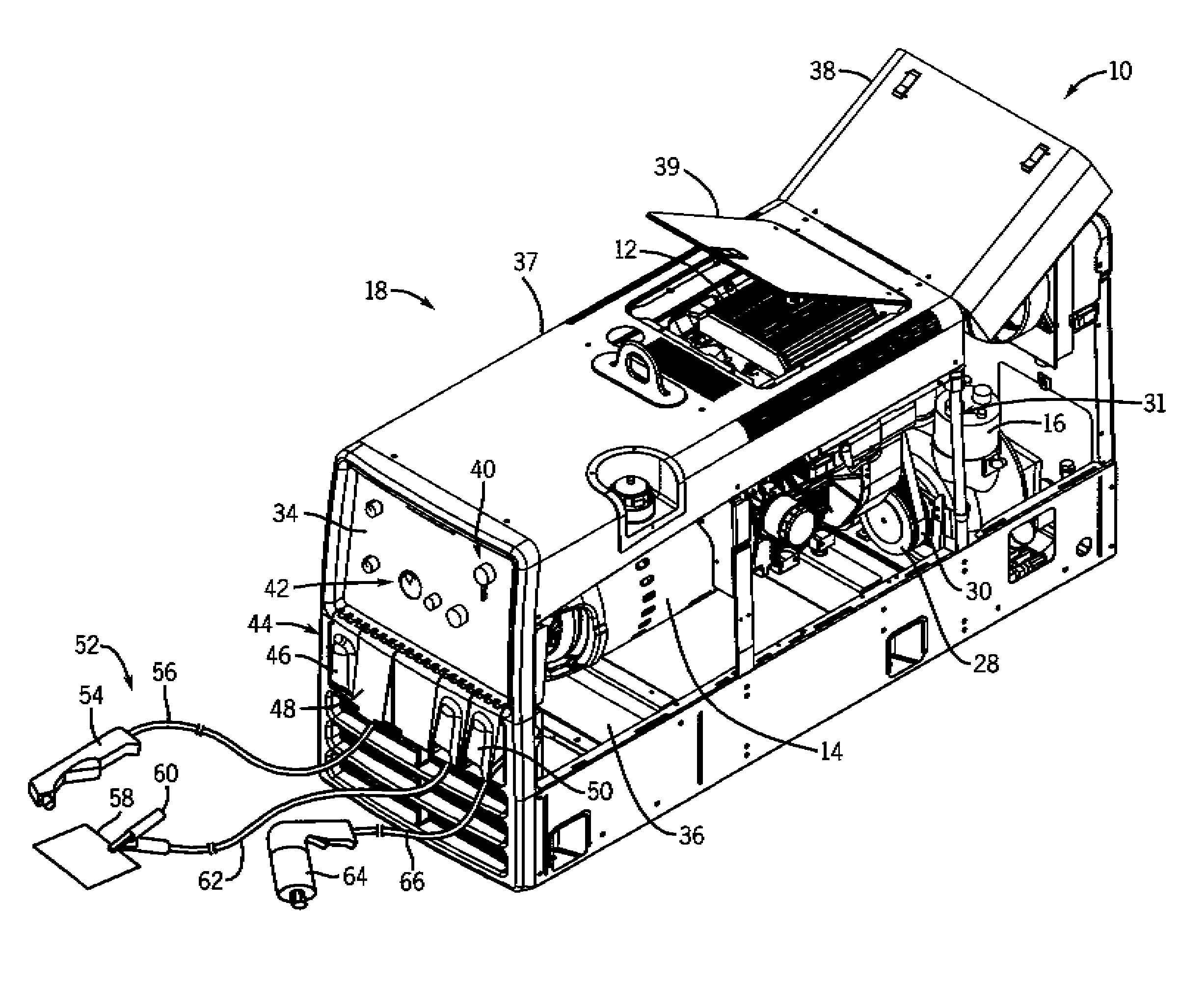
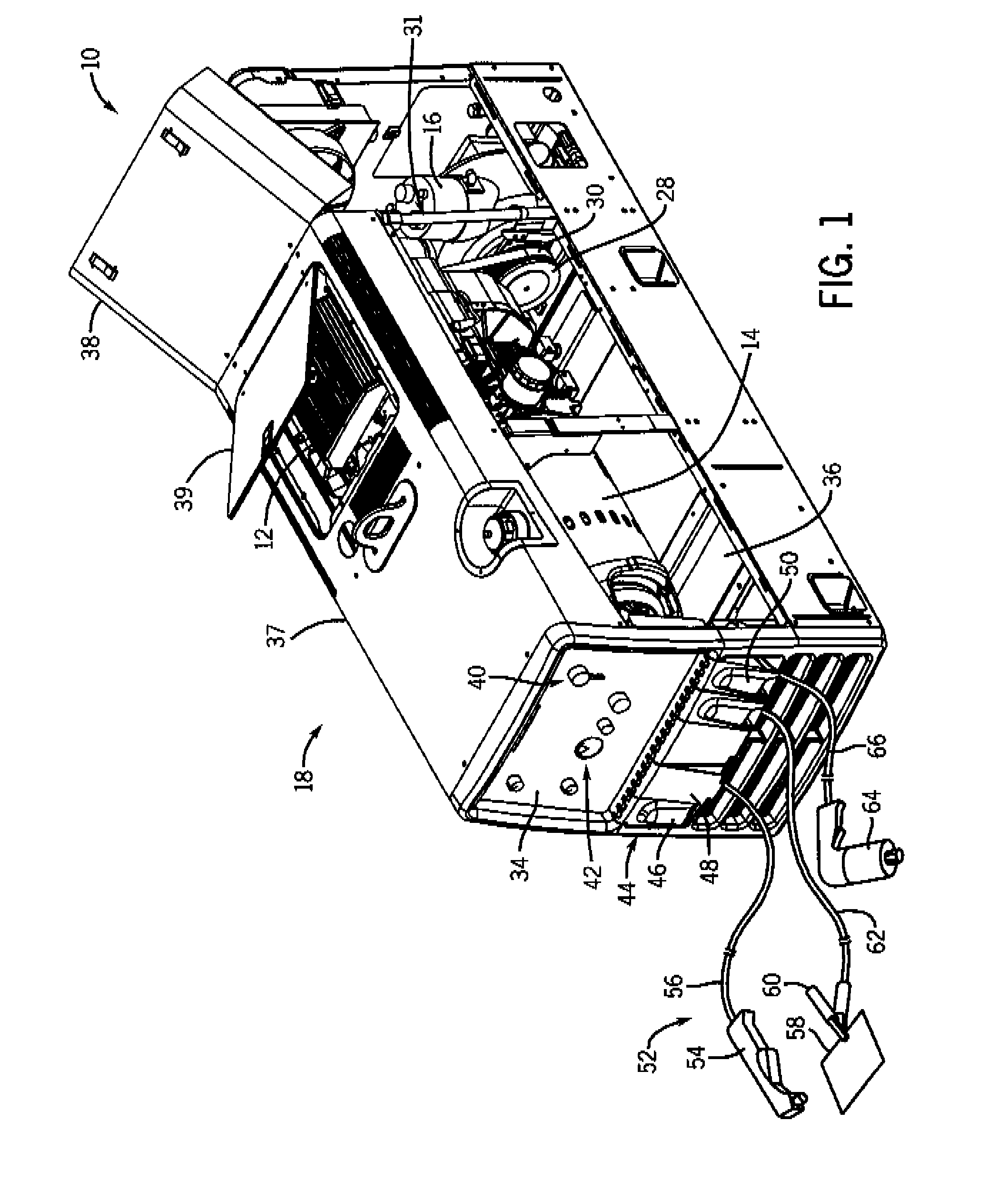
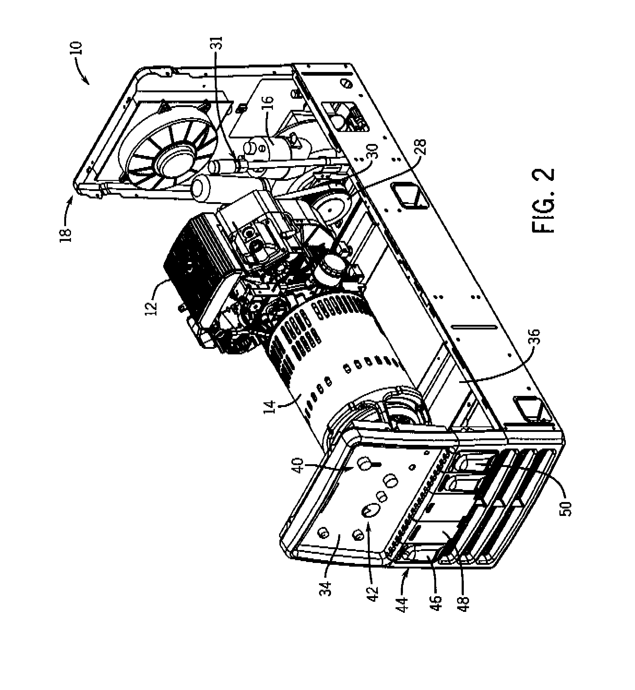
[0012]Referring now to the drawings, FIGS. 1-3 illustrate an engine-driven welding generator / compressor system 10 having an engine 12 drivingly coupled to a welding generator 14 and an air compressor 16 in a single enclosure 18 in accordance with an exemplary embodiment of the present technique. FIG. 1 is a partial perspective view of the system 10 with side access panels removed and top access panels or hatches rotated to open positions. FIG. 2 is another partial perspective view of the system 10 as illustrated in FIG. 1, wherein the entire top access panel assembly is removed to provide a better view of the internal features of the system 10FIG. 3 is a side view of the system 10 as illustrated in FIGS. 1 and 2. As depicted, the system 10 is configured to provide multiple outputs, including welding current, alternating current (AC) power, and compressed air.

[0013]As discussed in detail below, the illustrated system includes a variety of features to improve serviceability, reliabili...


PUM

PropertyMeasurementUnit
speedaaaaaaaaaa
mechanicalaaaaaaaaaa
electrical outputaaaaaaaaaa

Abstract

A system, in one embodiment, may include a portable unit having an engine, a generator coupled to the engine, a compressor coupled to the engine, and a priority load controller. The controller may be configured to adjust various loads on the engine, the generator, or the compressor, or a combination thereof, in response to sensor feedback and a priority control scheme. A computer-implemented method, in another embodiment, may include adjusting power output to various loads on an engine, a welding generator coupled to the engine, or an air compressor coupled to the engine, or a combination thereof, in a portable welding unit in response to sensor feedback and a priority control scheme.

Description

[0001]The invention relates generally to welding systems and more particularly to welding systems utilizing an engine coupled to an air compressor, a welding generator, and possibly other loads.[0002]Welding systems generally use an electrical current (e.g., welding current) to perform welding. The electrical current may be provided by an electrical power source (such as a power grid or battery) or an electrical generator coupled to a mechanical power source. Examples of mechanical power sources include engines that output power via a rotating drive shaft. Typically, the drive shaft is coupled to other devices that consume the energy provided by the rotating drive. For instance, welding systems often include internal combustion engines (such as gas or diesel engines) and an alternator or generator configured to convert the mechanical energy generated by the engine into electrical energy (e.g., electrical current). These systems are often referred to as engine-driven welding generato...

Claims


Application Information

Patent Timeline
Patent Type & Authority Applications(United States)
IPC IPC(8): B23K9/095B23K9/10
CPCB23K9/1006F02B63/02F02B63/04F02B63/048F02B63/06
Inventor FOSBINDER, DANIEL C.
Owner ILLINOIS TOOL WORKS INC
Why Eureka
Try Eureka