

Dispensing valve and a container for holding fluid provided with such a dispensing valve
- Summary
- Abstract
- Description
- Claims
- Application Information
AI Technical Summary
Benefits of technology
Problems solved by technology
Method used
Image

Examples
first embodiment
[0036]FIG. 2A shows cross-sectional view of a dispensing valve 1 according to the invention in closed position. FIG. 2B shows the dispensing valve 1 in open position.
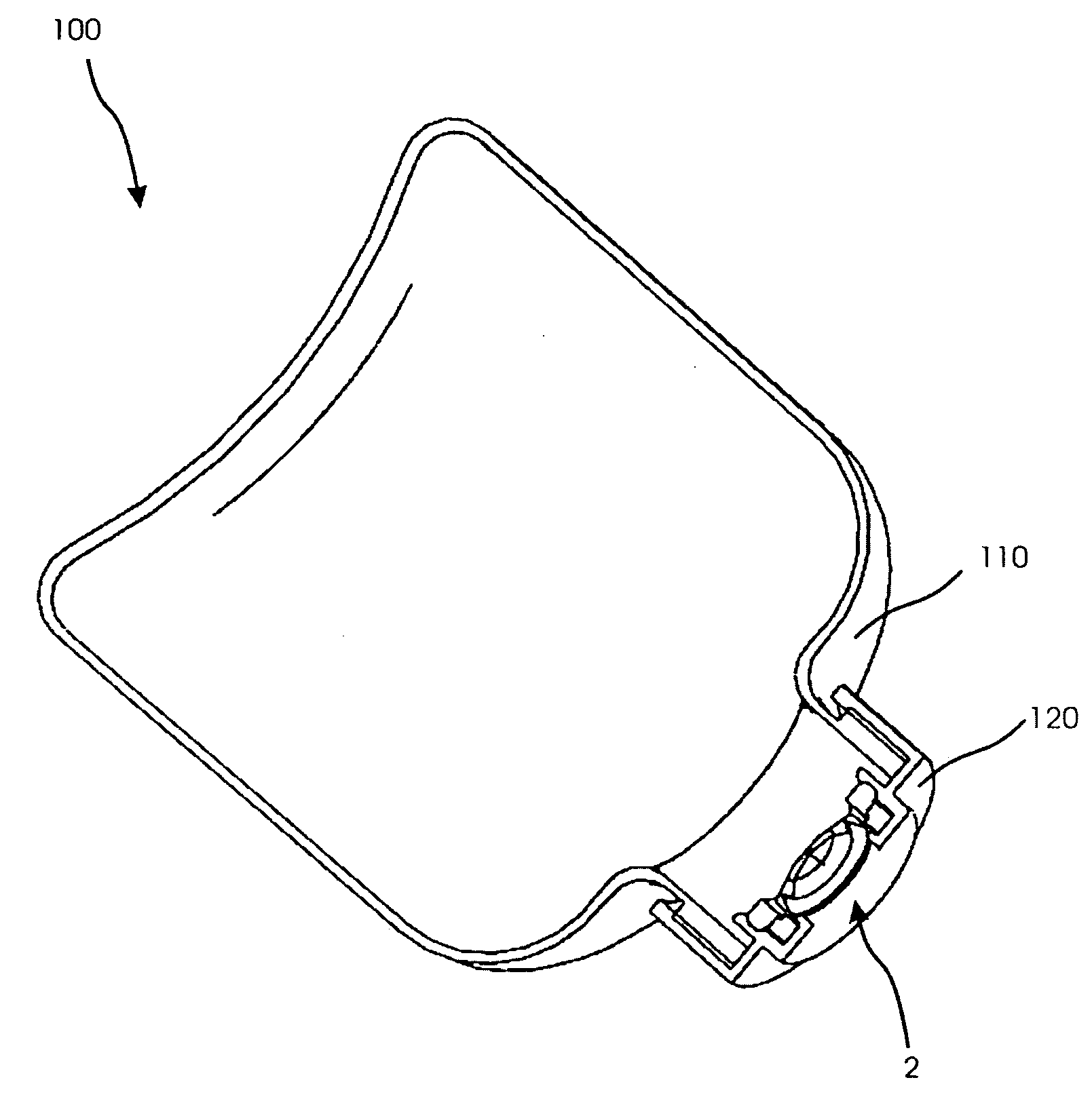
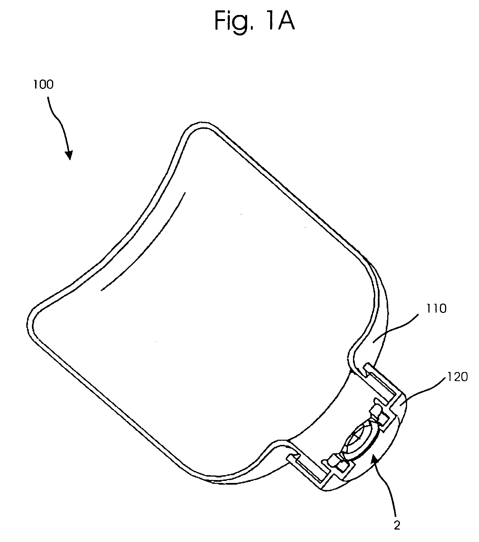
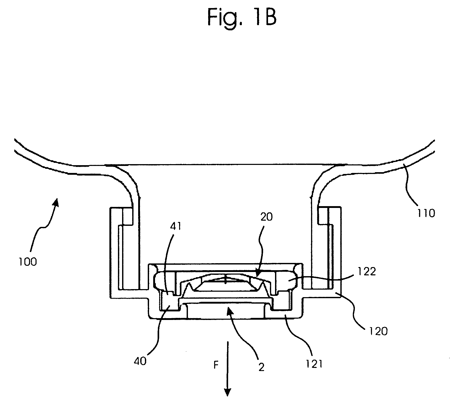
[0037]Dispensing valve 1 comprises a central member 10 that is provided with a flexible membrane 12 having at least one slit 13. A flange 40 surrounds the central member 10 for securing the valve 1 to a container (see FIGS. 1A and 1B) and is connected to the central member 10 by means of a material hinge 15.
[0038]A support 16 for the flexible membrane 12 forms part of the central member 10. In the secured position of the dispensing valve the support 16 is arranged such that it extends inwardly into the container. In the first embodiment shown the support 16 in the closed position extends substantially parallel to the inner wall of the container. The material hinge 15 directly couples the support 16 to the flange 40.
[0039]On the one side the material hinge 15 is located at the upper part of the flange 40, preferably at t...
second embodiment
[0043]FIG. 3A shows a cross-sectional view of a dispensing valve 20, which is a second embodiment according to the invention, in closed position. FIG. 3B shows the dispensing valve 20 in open position.
[0044]Dispensing valve 2 is largely similar to dispensing valve 1 described above. All reference numerals in FIGS. 3A and 3B are incremented with 10 when compared to the reference numerals of FIGS. 2A and 2B denoting equal parts.
[0045]In addition to dispensing valve 1 dispensing valve 2 is provided with a second material hinge 21 located on the central member 20 adjacent the support 26, between the support 26 and the slit 23.
[0046]On the central member 20 a first groove 24 is arranged for forming the second material hinge 21. Typically the shape of the groove 24 will be in conformance with the outer circumference of the central member of the valve. Preferably the groove 24 is annular shaped.
[0047]By means of the groove the support 26 is divided into two segments, 26A and 26B that are c...
third embodiment
[0050]FIG. 4A shows a cross-sectional view of a dispensing valve according to the invention in closed position. FIG. 4B shows the dispensing valve of FIG. 4A in open position.
[0051]Dispensing valve 3 is largely similar to dispensing valve 2 described above. All reference numerals in FIGS. 4A and 4B are incremented with 10 when compared to the reference numerals of FIGS. 3A and 3B denoting equal parts.
[0052]In addition to dispensing valve 2 dispensing valve 3 is provided with a third material hinge 37 arranged on the central member 30 between the second material hinge 34 and the center of the flexible membrane 32. In the embodiment shown the hinge 37 lies on the flexible membrane 32 and runs through the slit 33.
[0053]On the central member 30 a further groove 38 is arranged for forming the third material hinge 37. Typically the shape of the groove 38 will be in conformance with the outer circumference of the central member of the valve. Preferably the groove 38 is annular shaped.
[0054...
PUM
 Abstract
Description
Claims
Application Information