Using hydrostatic bearings for downhole applications

a technology of hydrostatic bearings and downholes, which is applied in the direction of drilling rods, drilling directional drilling, drilling pipes, etc., can solve the problems of bha vibration, drill bit damage, and limited depth by the mechanical strength of the drill pipe, so as to reduce the risk of vibration, low friction, and high load capacity

Inactive Publication Date: 2011-05-17
SCHLUMBERGER TECH CORP
View PDF8 Cites 11 Cited by
  • Summary
  • Abstract
  • Description
  • Claims
  • Application Information

AI Technical Summary

Benefits of technology

[0009]Use of hydrostatic bearings for downhole applications offers advantages over previous techniques. For example, hydrostatic bearings in stabilizer subs and steering assemblies provide low wear, low friction, high load capacity and simple, reliable design. Further, the pressure differential between the inside and the outside of the drill pipe can be used as a source of power to drive the hydrostatic bearings. Further, multi-pocket bearings can be utilized to enhance tolerance of surface imperfections in the formation.

Problems solved by technology

Maximum depth is limited by the mechanical strength of the drill pipe.
In particular, the depth is limited by the capability of the drill pipe to withstand the compressive, tensile, torsional, bending, and pressure differential forces required to create the borehole.
The decrease of torsional stiffness due to the extended length of the drill string in deep wells and the friction against the formation can even cause stick-slip effects which, in extreme cases, can lead to self-unscrewing of drill pipe joints, drill bit damage, BHA vibration, and other undesirable results.
In cases where surface or intermediate casings are already in place, friction between casing and drill string can wear through the casings at the pressure points of bends, resulting in either formation fluids entering the well or lost circulation.
Extensive forces of the drill pipe against the mud cake wall can lead to differential sticking and loss of equipment.
While such stabilizer subs reduce friction, they are relatively complex and costly.
Because of the complexity, such stabilizer subs are more likely to fail than simpler devices.
Ball bearing packages, for example, are particularly subject to degradation and failure in a borehole environment.
Non-rotating sleeves are also problematic when they become jammed against the formation downhole because the bearings themselves inhibit the use of torsionally applied force to free the sleeve.
The overall cost of use of such subs can be considerable because it is a multiple of stabilizer sub unit cost and the number of required subs.
However, the shape of the hydrodynamic sub requires very complex and expensive machining, rendering this solution uneconomical and impractical with current manufacturing techniques.
Furthermore, the Boulet hydrodynamic sub design only reduces friction when the drill string is rotating, and thus it will not provide assistance for restarting rotation after a new joint of drill pipe has been added at the surface.

Method used


Image

  • Using hydrostatic bearings for downhole applications
  • Using hydrostatic bearings for downhole applications
  • Using hydrostatic bearings for downhole applications

Examples


Embodiment Construction

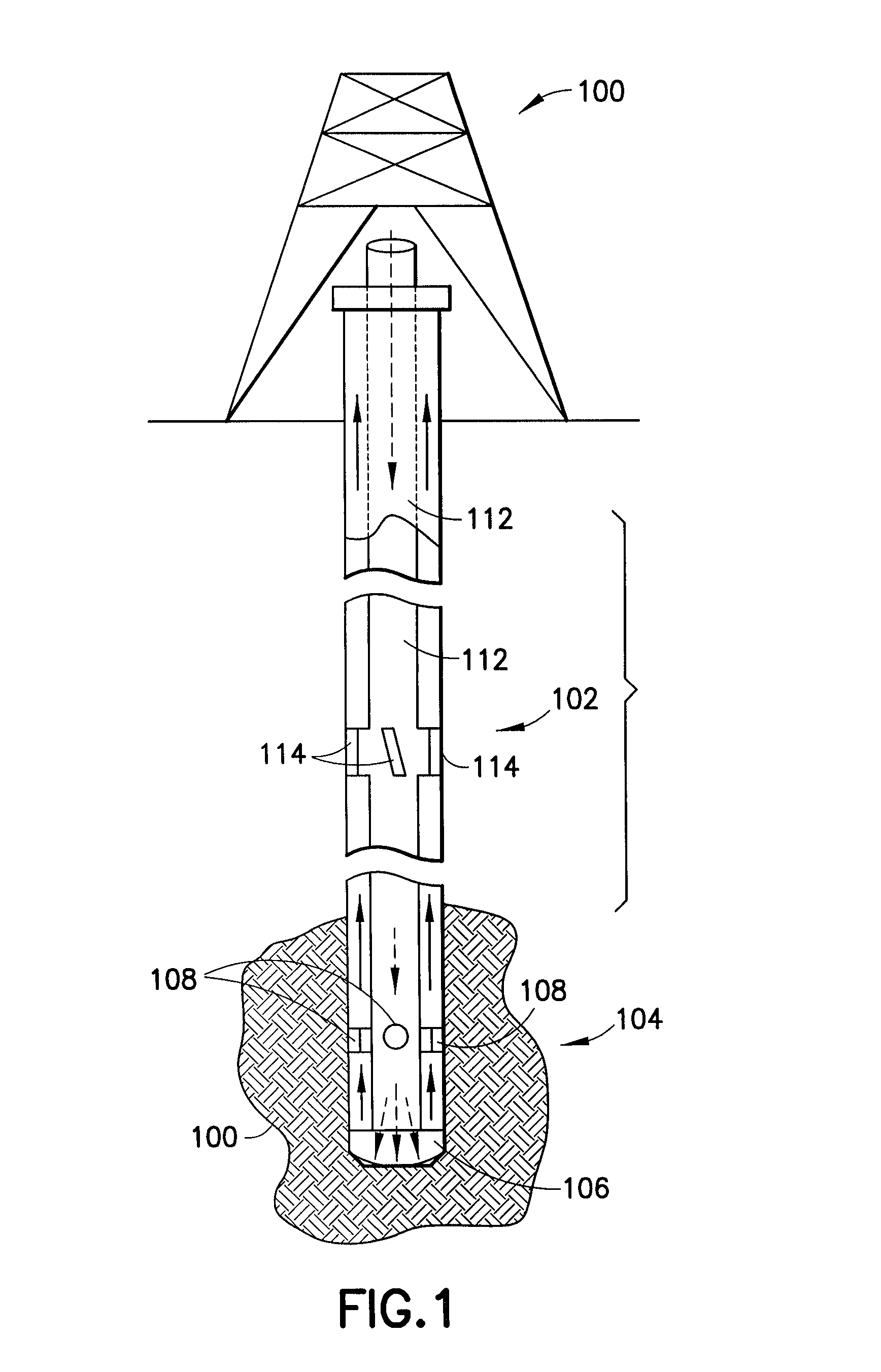
[0020]FIG. 1 illustrates a well drilling rig. The drilling rig includes a surface assembly (100), multiple stabilizer subs, of which stabilizer sub (102) is exemplary, and a bottom hole assembly (“BHA”) (104). The non-stationary sub-surface components of the drilling rig such as the drill pipe (112), stabilizer subs (102) and BHA (104) are typically referred to as the “drill string.” The BHA includes a drill bit (106) and at least one steering component (108), which may be disposed in the drill bit or higher on the BHA. The drill bit is operable to abrade the formation (110) in order to form a borehole. In particular, the drill bit forms a borehole having a greater diameter than the drill pipe (112) which makes up the majority of the length of the drill string.

[0021]In order to operate efficiently, the cuttings created by the drill bit are removed from the borehole by forcing highly pressurized water (“mud flow”) through openings in the drill bit, thereby forcing the cuttings to the...


PUM


Abstract

Hydrostatic bearings are used for drill string stabilization and bottom hole assembly steering. The hydrostatic bearings utilize an existing mud flow as the bearing fluid. For steering, the bearings may be used between movable kick pads and the formation to reduce friction. Alternatively, differential hydrostatic bearing pressure may be utilized to steer. Multi-modal (non-linear and linear) steering may be provided by selectively applying equal and unequal hydrostatic bearing pressures. The bearings can be made more tolerant of imperfections in the formation by utilizing multiple pressure pockets.

Description

FIELD OF THE INVENTION[0001]This invention relates generally to the field of well drilling, and more particularly to drill string stabilization and bottom hole assembly steering.BACKGROUND OF THE INVENTION[0002]The depth of oil wells drilled with current technology can reach tens of thousands of feet. The wells may be non-linear in order to increase exposure to the production zone. Maximum depth is limited by the mechanical strength of the drill pipe. In particular, the depth is limited by the capability of the drill pipe to withstand the compressive, tensile, torsional, bending, and pressure differential forces required to create the borehole. The pipe is subjected to torsional forces due to the torque required to overcome both friction against the formation and the torque to rotate the drill bit. The decrease of torsional stiffness due to the extended length of the drill string in deep wells and the friction against the formation can even cause stick-slip effects which, in extreme...

Claims


Application Information

Patent Timeline
Patent Type & Authority Patents(United States)
IPC IPC(8): E21B7/04
CPCE21B7/06E21B17/10E21B10/23
Inventor SIHLER, JOACHIM
Owner SCHLUMBERGER TECH CORP
Why Eureka
Try Eureka