Radar device

Inactive Publication Date: 2008-10-30
MITSUBISHI ELECTRIC CORP
View PDF10 Cites 52 Cited by
  • Summary
  • Abstract
  • Description
  • Claims
  • Application Information

AI Technical Summary

Benefits of technology

[0008]The present invention is directed to a solution to the above-described disadvantages and it is an object of the invention to provide a radar device capable of detecting a t

Problems solved by technology

However, the radar device disclosed by JP-A-2002-6041 must also include transmitting means for both s

Method used


Image

  • Radar device
  • Radar device
  • Radar device

Examples


first embodiment

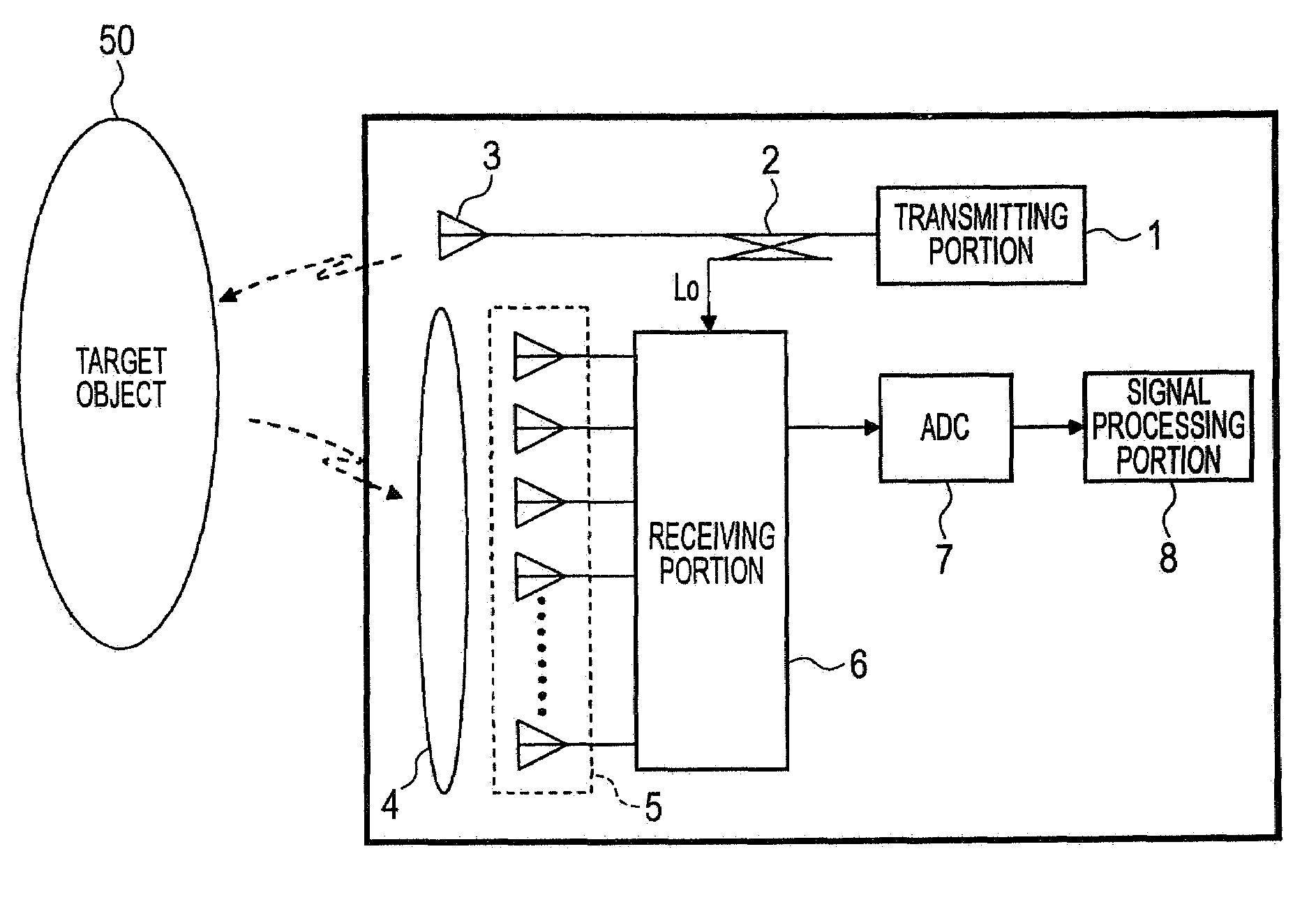
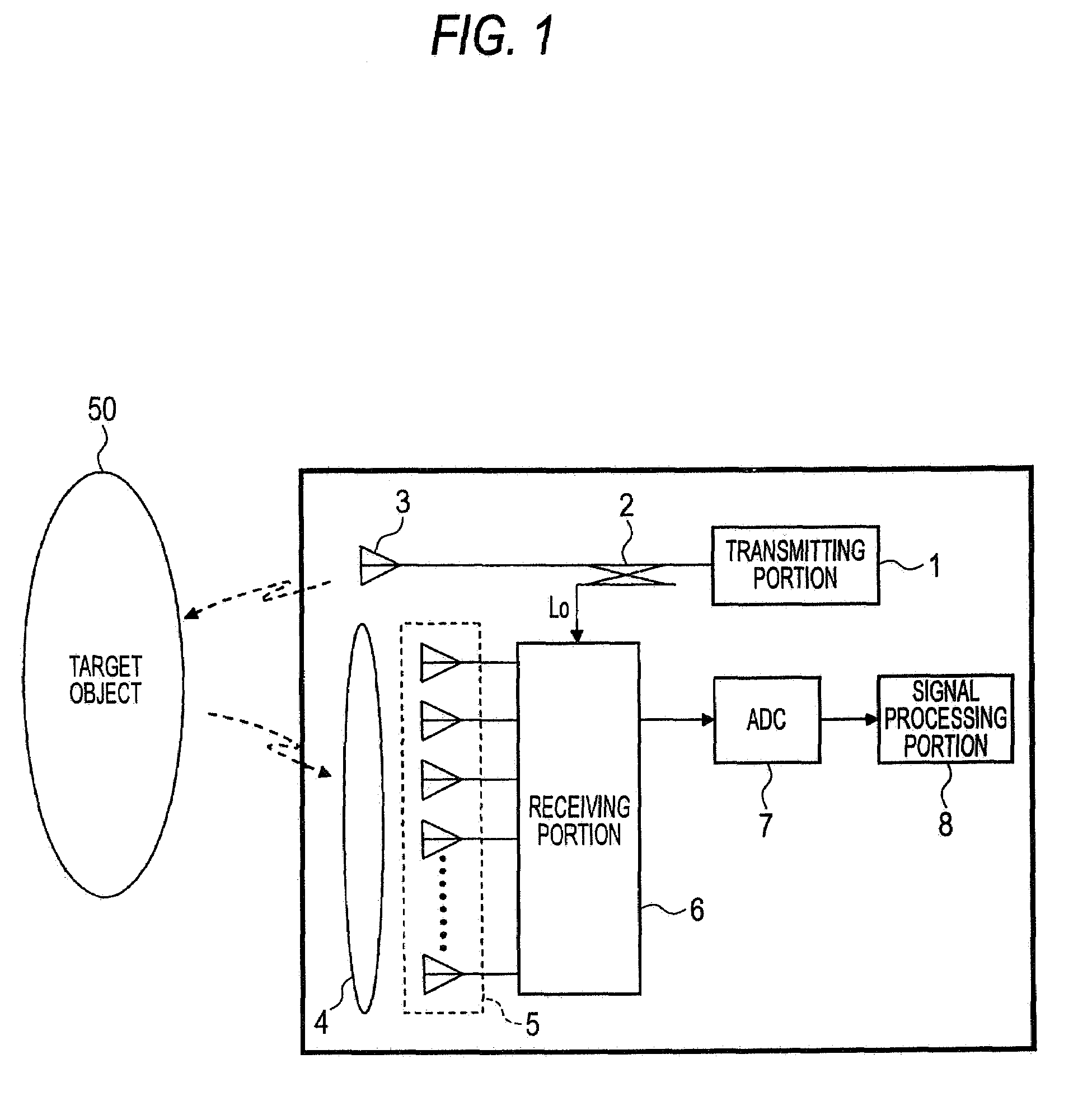
[0026]FIG. 1 is a schematic block diagram of the structure of a pulse type radar device according to a first embodiment of the invention.

[0027]The radar device 10 includes a transmitting portion 1 that outputs a pulse-modulated electromagnetic wave as a transmission signal, a directional coupler 2 that branches the output of the transmitting portion 1 into two, and a transmitting antenna 3 that radiates the output of the directional coupler 2 into the space.

[0028]The radar device 10 also includes a receiving antenna portion 5 including a plurality of antennas that receive the electromagnetic wave reflected by a target object 50 as a reception signal, a lens 4 that forms the reception beam width and direction of each antenna in the receiving antenna portion 5, and a receiving portion 6 that mixes the reception signal received by the receiving antenna portion 5 and a local signal Lo transmitted from the directional coupler 2 and extracts a beat signal.

[0029]The radar device 10 also in...

second embodiment

[0048]When a vehicle is stopped or travels at low speed, the vehicle control is mainly carried out to vehicles in the short distance and not to vehicles in the long distance. Therefore, vehicles in the long distance do not have to be detected. Therefore, if the vehicle is stopped or travels at low speed, target objects in the long distance are not detected and only those in the short distance are detected.

[0049]Now, the processing will be described with reference to the flowchart in FIG. 13. Steps 101 to 104 and 106 to 110 are the same as those in FIG. 13.

[0050]If it is determined in step S103 that the beam being processed is not a short distance beam, it is determined in step S111 whether the vehicle is stopped or travels at low speed. If it is determined in step S111 that the vehicle is stopped or travels at low speed, the maximum range gate number for processing is set to 10 in step S112 and in the following processing from steps S106 to S108, detection processing to target objec...

third embodiment

[0052]A radar device according to a third embodiment includes a preceding vehicle determining portion 9 that determines a preceding vehicle among detected target objects as shown in FIG. 14. The vehicle control, for example, in a following distance control system is generally carried out to the nearest preceding vehicle, and therefore data about vehicles existing ahead of the preceding vehicle is not used in the control. Therefore, in the long distance region ahead of the preceding vehicle detected by the preceding vehicle determining portion 9, target objects are not detected. In the short distance behind the preceding vehicle, the detection angle range may be widened so that vehicles coming to cut in can be surely detected.

[0053]Note that the preceding vehicle determining portion as described above is disclosed for example by JP-A-8-279099.

[0054]According to the third embodiment, detection of target objects is not carried out in the long distance ahead of the preceding vehicle, an...


PUM


Abstract

A radar device capable of detecting a target object by itself only in a range required by a vehicle control system by changing the detection angle depending on the distance without changing the hardware structure is provided. The radar device includes transmitting means for transmitting an electromagnetic wave as a transmission signal, receiving means for receiving the electromagnetic wave reflected from the target object as a reception signal, and signal processing means for detecting a target object existing around the vehicle from the transmission signal and the reception signal, and calculating the relative position and the relative speed between the object and the vehicle. The detection angle is changed depending on the distance for measurement, so that the target object is detected only in a region necessary in operating the vehicle control system.

Description

BACKGROUND OF THE INVENTION[0001]1. Field of the Invention[0002]The present invention relates to a radar device provided in a vehicle to detect a target object existing around the vehicle and measure the relative position and the relative speed between the vehicle and the object.[0003]2. Description of the Related Art[0004]A radar device provided in a vehicle transmits an electromagnetic wave as a transmission signal, receives the electromagnetic wave reflected by a target object as a reception signal, and measures the relative position and the relative speed between the vehicle and the target object based on the transmission signal and the reception signal. The radar device is used in a vehicle control system such as a following distance control system used to control the distance between the vehicle and the preceding vehicle and a jam tracking system that allows the vehicle to follow the preceding vehicle during a traffic jam.[0005]Such a vehicle control system must generally dete...

Claims


Application Information

Patent Timeline
IPC IPC(8): G01S13/00B60R21/00G01S13/931
CPCB60W40/04B60W2420/52G01S13/18G01S13/48G01S13/931
Inventor AKITA, KENICHI
Owner MITSUBISHI ELECTRIC CORP
Why Eureka
Try Eureka