Lens system for traffic signal lighting

Inactive Publication Date: 2008-10-30
POWER SIGNAL TECH
View PDF2 Cites 6 Cited by
  • Summary
  • Abstract
  • Description
  • Claims
  • Application Information

AI Technical Summary

Benefits of technology

[0004]The present invention achieves technical advantages as a traffic light compound lens system. One embodiment of the invention utilizes two Fresnel lenses to provide a more efficient lens system with better light directing capabilities than a single lens syste

Problems solved by technology

However this lens system is not the most efficient system and for large off axis viewing distanc

Method used


Image

  • Lens system for traffic signal lighting
  • Lens system for traffic signal lighting
  • Lens system for traffic signal lighting

Examples


Example

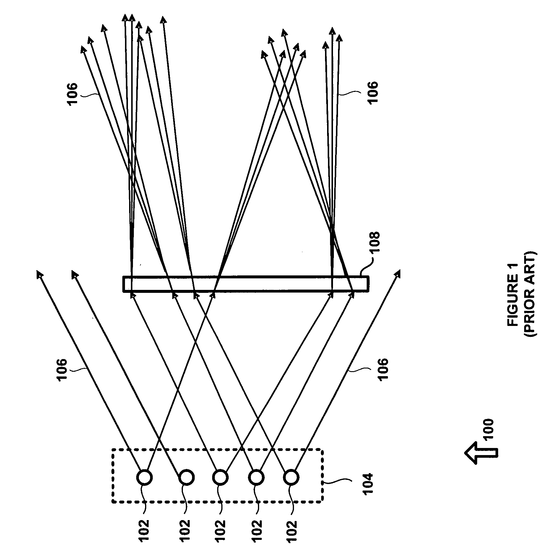
[0007]Referring to FIG. 1, there is shown at 100 a traditional traffic light single lens system. A light source, such as LED array 104 with a plurality of LEDs 102, generates light 106 for use in traffic signals. Light 106 propagates through Fresnel lens 108, which provides a large aperture and a short focal length, and continues to a viewer. The purpose of LED array 104 and Fresnel lens 108 is to selectively direct light 106 to groups of lanes on the street. Some of light 106 is wasted, as shown by light 106 missing Fresnel lens 108, and leads to a dim or partially illuminated signal to the viewer.

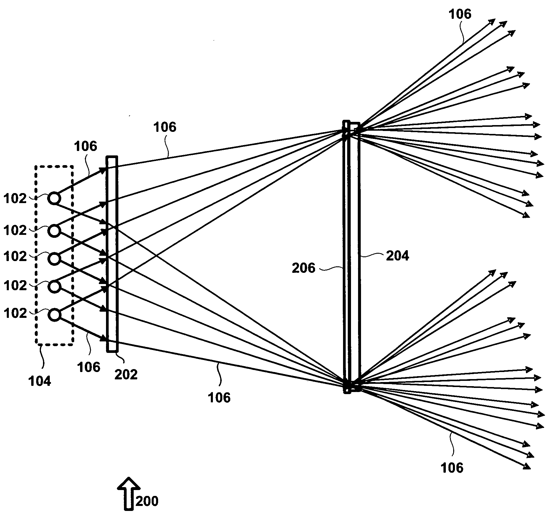
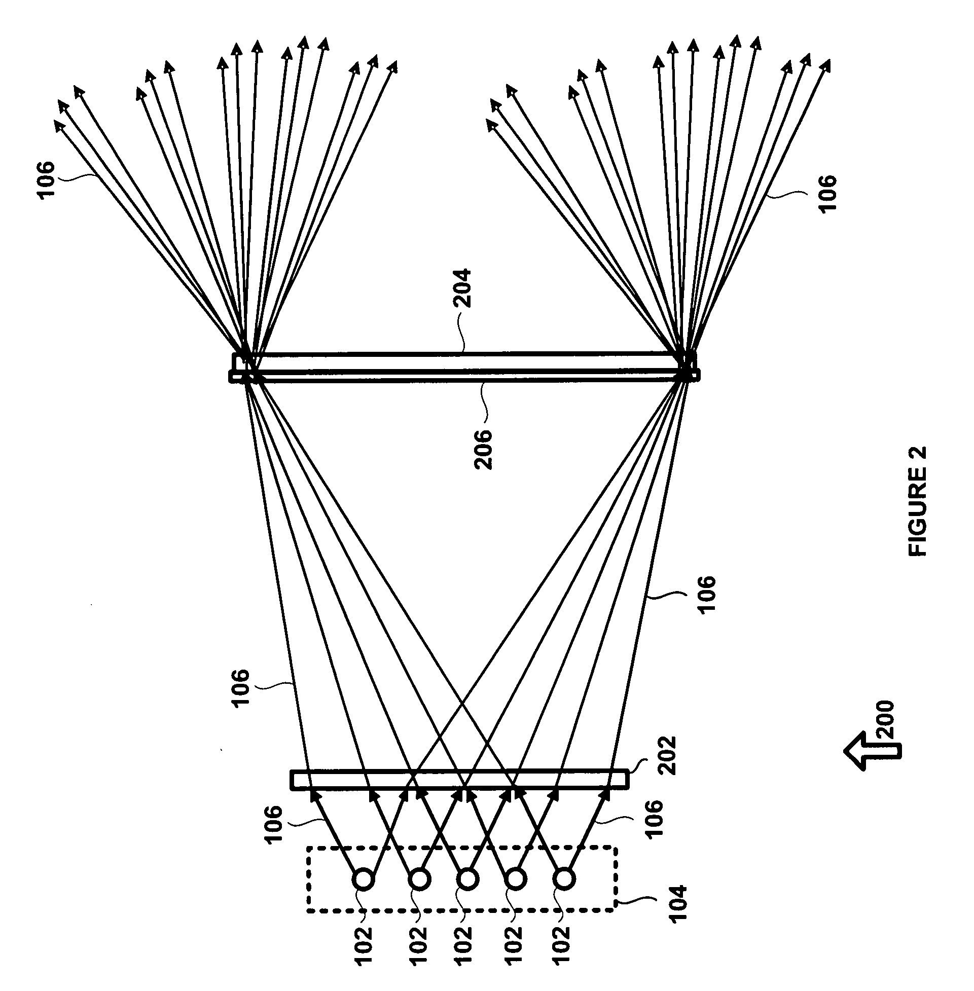
[0008]Referring now to FIG. 2, there is shown at 200 a traffic light compound lens system in accordance with an exemplary embodiment of the present invention. The compound lens system 200, consists of LED array 104, first Fresnel lens 202, and second Fresnel lens 204. First Fresnel lens 202 is closest to LED array 104 and second Fresnel lens 204 is furthest from LED array 104. Second Fres...


PUM


Abstract

A traffic light compound lens system is presented that utilizes two Fresnel lenses to provide a more efficient lens system with better light directing capabilities than a single lens system. The optical power of each Fresnel lens is less than that required for the single lens system. Due to aberration reduction, the compound lens system has less geometrical aberration than a single lens system, especially over a larger field of view, and has improved directionality. In addition, the compound lens system has better collection efficiency.

Description

FIELD OF THE INVENTION[0001]The present invention is generally related to traffic signaling, and more specifically to a lens system adapted to direct light from an array of light emitting diodes (LEDs) in a traffic signal.BACKGROUND OF THE INVENTION[0002]In modem traffic signals it is desirable to signal different traffic lanes and therefore traffic signals are required to independently send out signal light. In addition for power efficiency and cost reduction the new bright LEDs are being used. To make efficient use of the light from an LED array it is necessary to use a lens, typically a Fresnel lens, so that light can be collimated and sent to the street as shown in FIG. 1. The Fresnel lens collimates, or nearly so, the light from the LEDs. In order to have a fully illuminated signal as seen by a viewer, a scattering surface is often added to the rear surface of the Fresnel lens.[0003]However this lens system is not the most efficient system and for large off axis viewing distanc...

Claims


Application Information

Patent Timeline
IPC IPC(8): G02B3/08G02B5/02
CPCG02B3/08G08G1/095
Inventor SASIAN-ALVARADO, JOSE MANUEL
Owner POWER SIGNAL TECH
Why Eureka
Try Eureka