
Method and apparatus for testing building materials

a technology for building materials and methods, applied in the field of testing equipment, can solve the problems of large number of tests, three to four week delay, and inconvenient procedure, and achieve the effect of reducing costs and improving the turn-around time for conducting tests

Active Publication Date: 2008-10-30
HENRY WDG
View PDF5 Cites 12 Cited by
  • Summary
  • Abstract
  • Description
  • Claims
  • Application Information

AI Technical Summary

Benefits of technology

[0021]A primary advantage of the invention resides in the ability to pre-test samples of construction materials before submission to a testing laboratory.
[0022]Another advantage offered by the present disclosure is the reduced cost.
[0023]Another advantage of the invention resides in the improved turn-around time to conduct the tests.
[0024]Still another advantage resides in the ease with which the testing may be undertaken, along with the ability to preheat the test chamber, weigh the combustion fuel used, and measure the flame progression during the test.
[0025]Still other advantages and benefits of the present disclosure will become apparent to one skilled in the art upon reading and understanding the following detailed description.

Problems solved by technology

If the manufacturer finds the sample does not achieve the desired ratings as a result of conducting these tests, the manufacturer is relegated to creating new samples for submission and undertaking additional tests.
This procedure can become cost prohibitive, For example, development of a new building material may result in a large number of tests as the manufacturer “tweaks” the formulation of the product.
Creating the sample and shipping the samples to the test laboratories may cost between three and five thousand dollars ($3,000-$5,000) per sample, and even then there is a three to four week delay in order to have the test completed.

Method used


Image

  • Method and apparatus for testing building materials
  • Method and apparatus for testing building materials
  • Method and apparatus for testing building materials

Examples


Embodiment Construction

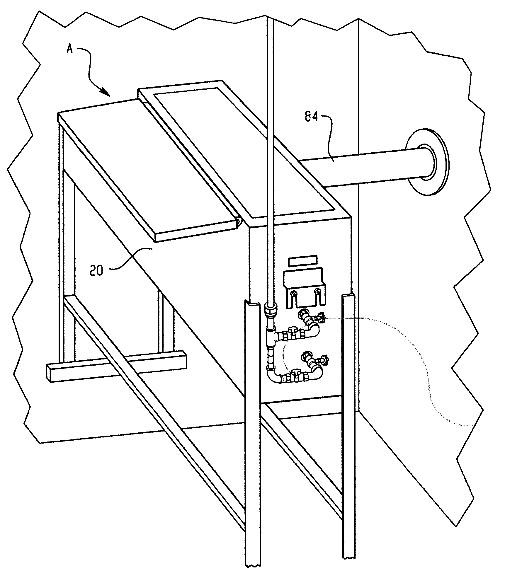
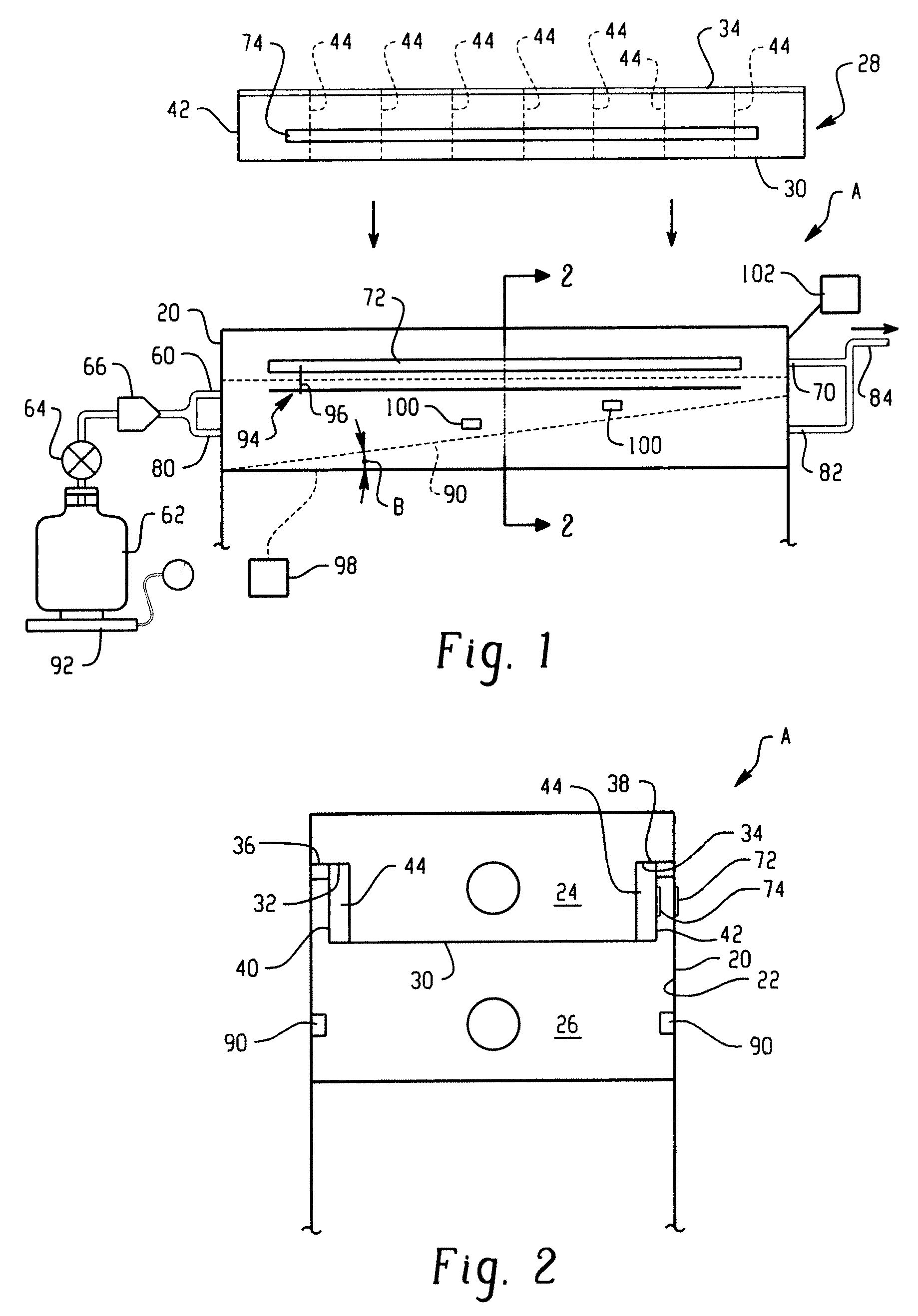
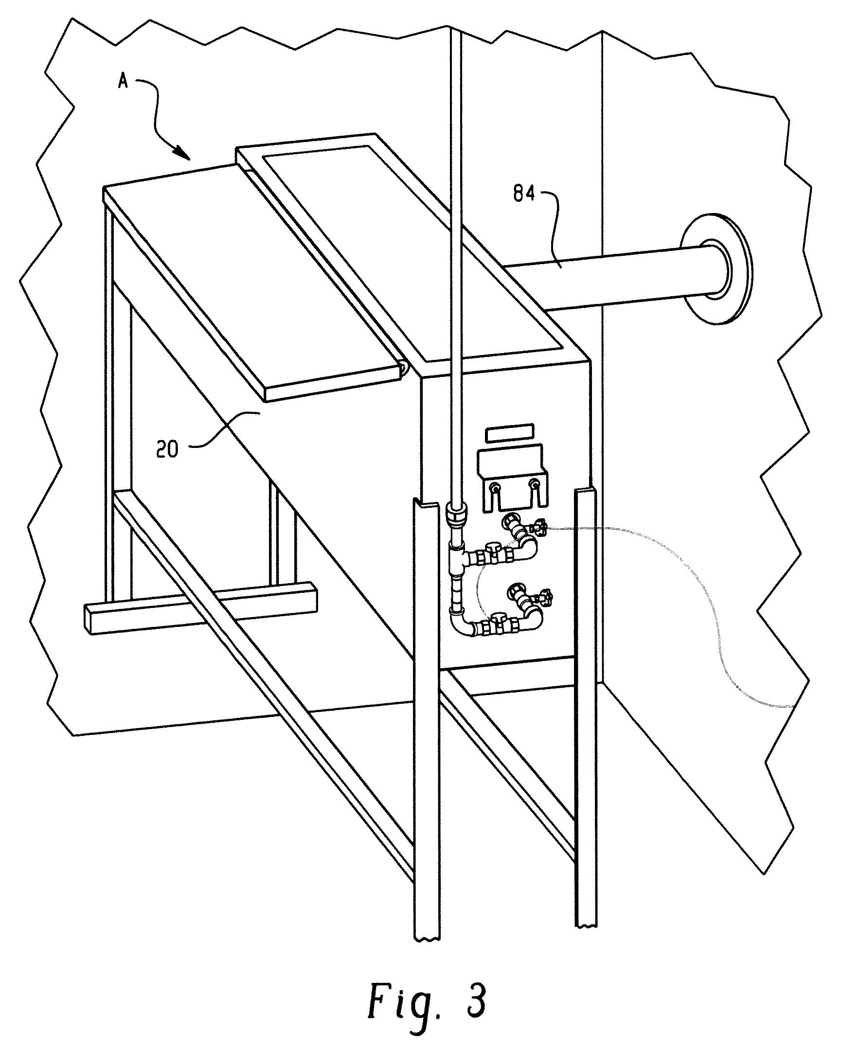
[0031]FIG. 1 shows a test apparatus A that includes a housing 20 that has an internal chamber 22. The internal chamber is preferably divided into first and second portions 24, 26 by an insert 28 that includes a wall 30 that extends along a longitudinal extent of the chamber when the insert is received in the housing. Particularly, flanges 32, 34 of the insert are supported on shoulders 36, 38 in the housing. The flanges extend outwardly from sidewalls 40, 42 of the insert. Further, baffles 44 may be provided in the insert, and preferably extend inwardly from the sidewalls 40, 42 at longitudinally spaced locations along the length of the insert.

[0032]As best illustrated in FIG. 2, when the insert is mounted in the housing 20, bottom wall 30 defines the chamber 22 into the first and second portions 24, 26. With reference again to FIG. 1, a first or upper inlet 60 is disposed at one end of the upper or chamber first portion 24. The first inlet communicates with a combustion fuel source...


PUM


Abstract

An apparatus (A) for testing an associated construction material sample includes a housing (20) having an internal chamber (22) divided by a wall portion (30) into first and second portions (24, 26). A support in the housing is dimensioned to mount an associated construction material sample therein. A first burner (60) communicates with first portion of the housing for supplying a flame thereto. A second burner (80) communicates with the second portion of the housing for preheating the first portion. The testing method of an associated construction material sample includes installing the sample in the housing, preheating the housing, introducing a flame toward the sample, monitoring the flame as combustion progresses longitudinally along the sample, and recording data regarding the flame progression. The method further includes weighing fuel used for combustion in order to calculate BTU input to the test chamber, may also include using a remote (98) to actuate a recording member (94) that is selectively advanced as the flame spreads, and may further include providing a continuous window along the housing through which the flame can be viewed.

Description

[0001]This application claims the priority benefit of, and expressly incorporates the entire disclosure of U.S. provisional application Ser. No. 60 / 920,470, filed Mar. 28, 2007.BACKGROUND OF THE INVENTION[0002]This application relates to a testing apparatus, and more particularly to an apparatus for flame testing of materials such as building materials. It finds particular application in testing polyurethane roofing or insulation, but should not be limited to these particular building materials. Thus, the method and apparatus may find use with regard to related materials and testing.[0003]It is common to expose building materials to combustion, and particularly test a sample under controlled procedures in order to determine the relative burning behavior as typically measured by the spread of the combustion flame, as well as measuring smoke that is developed during the test. For example, ASTM Standard E 84-06 entitled “Standard Test Method for Surface Burning Characteristics of Build...

Claims


Application Information

Patent Timeline
IPC IPC(8): G01N25/00
CPCG01N25/22
Inventor WEST, RICHARD A.ROSECRANS, MICHAEL R.
Owner HENRY WDG
Learn More