Compliant Foil Fluid Film Radial Bearing Or Seal

a technology of fluid film bearing and sealing, which is applied in the direction of bearings, shafts and bearings, rotary bearings, etc., can solve the problems of increasing fluid pressure, bearing wear, and coulomb damping of any axial direction

Active Publication Date: 2008-10-30
CAPSTONE TURBINE
View PDF28 Cites 26 Cited by
  • Summary
  • Abstract
  • Description
  • Claims
  • Application Information

AI Technical Summary

Benefits of technology

[0016]The present invention is directed to a compliant foil fluid film radial bearing or seal having a segmented outer bushing which allows the bearing or seal to be broken down i

Problems solved by technology

This results in increases in fluid pressure, especially near the trailing end of the wedge channels.
Flexing and sliding of the foils against each other and against the bushing causes coulomb damping of any axial or overturning m

Method used


Image

  • Compliant Foil Fluid Film Radial Bearing Or Seal
  • Compliant Foil Fluid Film Radial Bearing Or Seal
  • Compliant Foil Fluid Film Radial Bearing Or Seal

Examples


Embodiment Construction

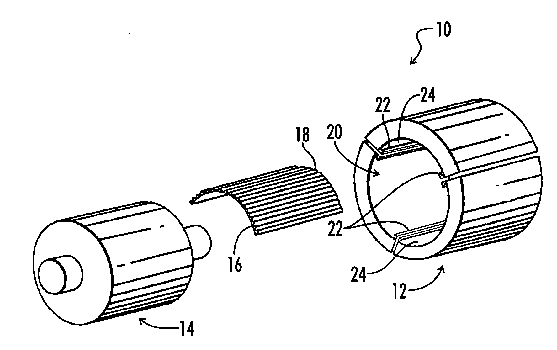
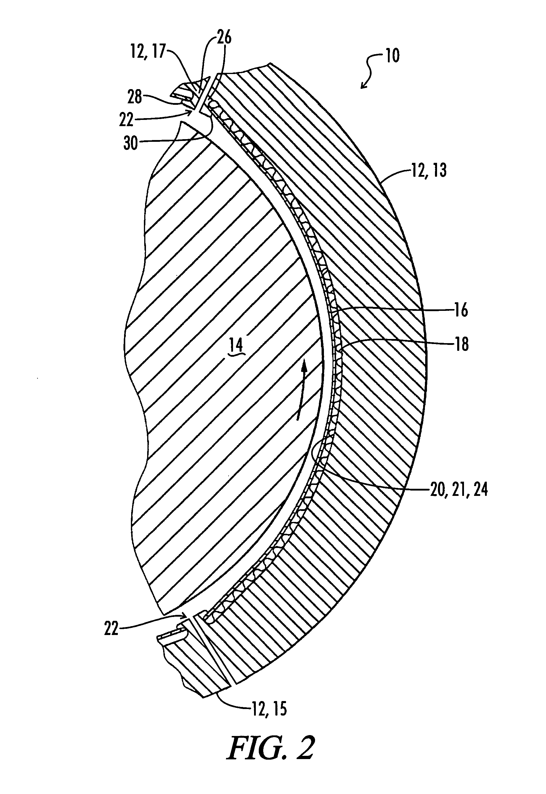
[0042]Illustrated in FIGS. 1-3 is a first embodiment of the compliant foil fluid film radial bearing and / or seal apparatus 10 of the present invention. This apparatus 10 generally comprises a bushing 12, a shaft or rotor 14, a plurality of compliant foils 16 (shown as three), and a like plurality of foil undersprings 18.

[0043]The bushing 12, which may also be referred to as a cartridge 12, is made up of a plurality of peripherally separate bushing segments 13, 15 and 17. The bushing 12 has an interior bore 20 defined therethrough with peripheral portions 21, 23 and 25 of bore 20 being defined on the bushing segments 13, 15 and 17, respectively. It is noted that when the bushing segments 13, 15 and 17 are described herein as peripherally separate, that means only that the segments can be separated from each other. It does not mean that they are spaced apart as shown in FIG. 12; they may engage and even overlap as shown in FIG. 5.

[0044]The interior bore 20 of the bushing 12 includes a...


PUM


Abstract

A compliant foil fluid film bearing or seal apparatus includes a bushing having a plurality of peripherally separate bushing segments. The bushing has a bore defined therethrough, with a peripheral portion of the bore being defined on each bushing segment. A plurality of compliant foils is carried by the bushing, with at least one of the compliant foils being disposed on each bushing segment. A plurality of foil undersprings is disposed beneath the plurality of compliant foils.

Description

BACKGROUND OF THE INVENTION[0001]1. Technical Field[0002]This invention relates to the general field of compliant foil fluid film bearings and seals.[0003]2. Background Art[0004]Compliant foil fluid film radial bearings are currently being utilized in a variety of high speed rotor applications. These bearings are generally comprised of a bushing, a rotating element such as a rotor or shaft adapted to rotate within the bushing, non-rotating compliant fluid foil members mounted within the bushing and enclosing the rotating element, and non-rotating compliant spring foil members mounted within the bushing underneath the non-rotating compliant fluid foil members. The space between the rotating element and the bushing is filled with fluid (usually air) which envelops the foils. Conventionally, the compliant fluid foil elements are divided into a plurality of individual compliant foils to form a plurality of wedge shaped channels which converge in thickness in the direction of the rotatio...

Claims


Application Information

Patent Timeline
IPC IPC(8): F16C32/06
CPCF16C17/024F16C43/02F16C33/046F16C2360/23F16C27/02
Inventor WADE, JONATHANLUBELL, DANIEL
Owner CAPSTONE TURBINE
Why Eureka
Try Eureka