
System, apparatus and method for controlling multicast flow in passive optical network

a passive optical network and multicast flow technology, applied in data switching networks, multiplex communication, digital transmission, etc., can solve the problems of inability to judge whether a user is joining an authorized or an unauthorized multicast group, failure to filter unauthorized multicast data, etc., to improve business income and enhance the multicast security of the gpon system

Active Publication Date: 2008-10-30
HUAWEI TECH CO LTD
View PDF11 Cites 15 Cited by
  • Summary
  • Abstract
  • Description
  • Claims
  • Application Information

AI Technical Summary

Benefits of technology

[0029]An embodiment of the present invention provides a system, apparatus and method for controlling multicast flows in a passive optical network to prevent an ONT from receiving unauthorized multicast data, and enhance multicast security of the whole GPON system.
[0051]The present invention solves the problem in the prior art that flows of unauthorized multicast group can be received when a user is added into an unauthorized multicast group in a PON system. Receiving unauthorized multicast data at ONT is prohibited, which enhances the multicast security of the GPON system. For IPTV providers, the present invention can prevent users from watching unauthorized programs, and thus improves business income.

Problems solved by technology

Under the current standard, in the case that an ATM PVC or a GEM port carries multiple multicast groups, since the IGMP snooping of ONT restricts only the port which is adapted to transmit the multicast flows, it is not possible to judge whether a user is joining an authorized or an unauthorized multicast group.
In other words, it fails to filter the unauthorized multicast data.

Method used


Image

  • System, apparatus and method for controlling multicast flow in passive optical network
  • System, apparatus and method for controlling multicast flow in passive optical network
  • System, apparatus and method for controlling multicast flow in passive optical network

Examples


Embodiment Construction

[0064]The present invention will be further described with reference to the accompanying figures and embodiments.

I. The Introduction of Multicast Right Control Point

[0065]Depending on the location of an ONT, the ONT is capable of providing service for a single family user (FTTH mode) or multiple family users (FTTB mode).

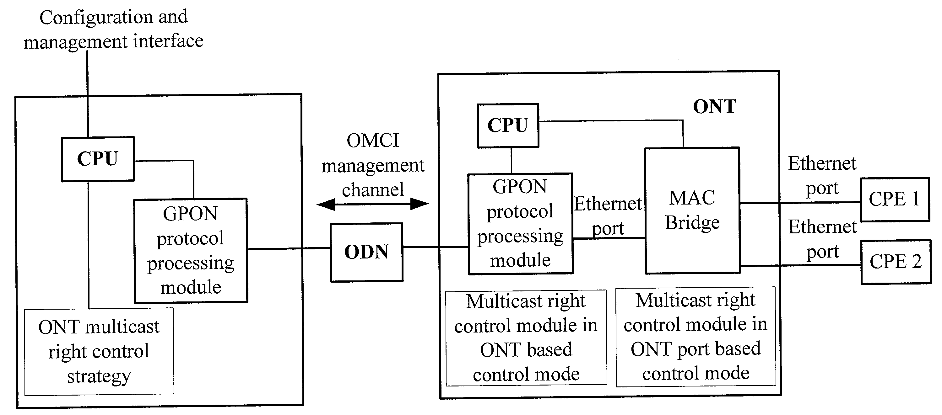
[0066]As shown in FIG. 7, if the ONT serves multiple family users connected with the ONT through Ethernet ports and each family user has a different multicast right, the multicast right control points shall be located on the Ethernet port (as indicated by ‘A’ in the figure) providing access to the user;

[0067]FIG. 8 shows control points in the case that an ONT serves a single user while each CPE has a different multicast right. In the case that the ONT only serves a single family user, the ONT accesses multiple CPEs of the single family user through Ethernet ports. If each device connecting to the Ethernet ports has a different multicast right, i.e., each CPE has a se...


PUM


Abstract

The present invention discloses a method for controlling multicast flow in passive optical network includes: receiving multicast data from the optical line terminal, determining whether the received multicast data satisfies a multicast right control condition, transmitting the multicast data to the user side if the received multicast data satisfies the multicast right control condition, or discarding the multicast data if the received multicast data does not satisfy the multicast right control condition. The present invention also discloses an optical network terminal, an optical line terminal, and a system consisting of an optical network terminal and an optical line terminal and an optical distribute network, which implement the above mentioned method. The present invention could prevent the optical network terminal from receiving illegal multicast data and enhance the multicast security of the whole passive optical network system.

Description

CROSS-REFERENCE TO RELATED APPLICATIONS[0001]This application is a continuation of International Patent Application No. PCT / CN2006 / 002803, filed Oct. 20, 2006, which claims priority to Chinese Patent Application No. 200610032696.1, filed Jan. 4, 2006, both of which are hereby incorporated by reference in their entirety.FIELD OF THE INVENTION[0002]The present invention relates to a technology in a passive optical network, especially to a system, apparatus and method for controlling multicast flow in a passive optical network.BACKGROUND OF THE INVENTION[0003]Broadband access technology mainly includes copper access technology (such as various digital subscriber line (DSL) technology) and optical access technology. The access network implemented by optical access technology is referred to as Optical Access Network (OAN). Based on different network deployment methods, OAN is classified into Fiber to The Home (FTTH), Fiber to The Building (FTTB), Fiber To The Business (FTTBusiness), Fibe...

Claims


Application Information

Patent Timeline
Patent Type & Authority Applications(United States)
IPC IPC(8): H04J14/00
CPCH04L12/185H04L45/00H04L63/104H04Q11/0067H04Q2011/0064
Inventor NIU, LEHONG
Owner HUAWEI TECH CO LTD
Learn More