
Fitting device

Inactive Publication Date: 2008-10-30
FANUC LTD
View PDF3 Cites 29 Cited by
  • Summary
  • Abstract
  • Description
  • Claims
  • Application Information

AI Technical Summary

Benefits of technology

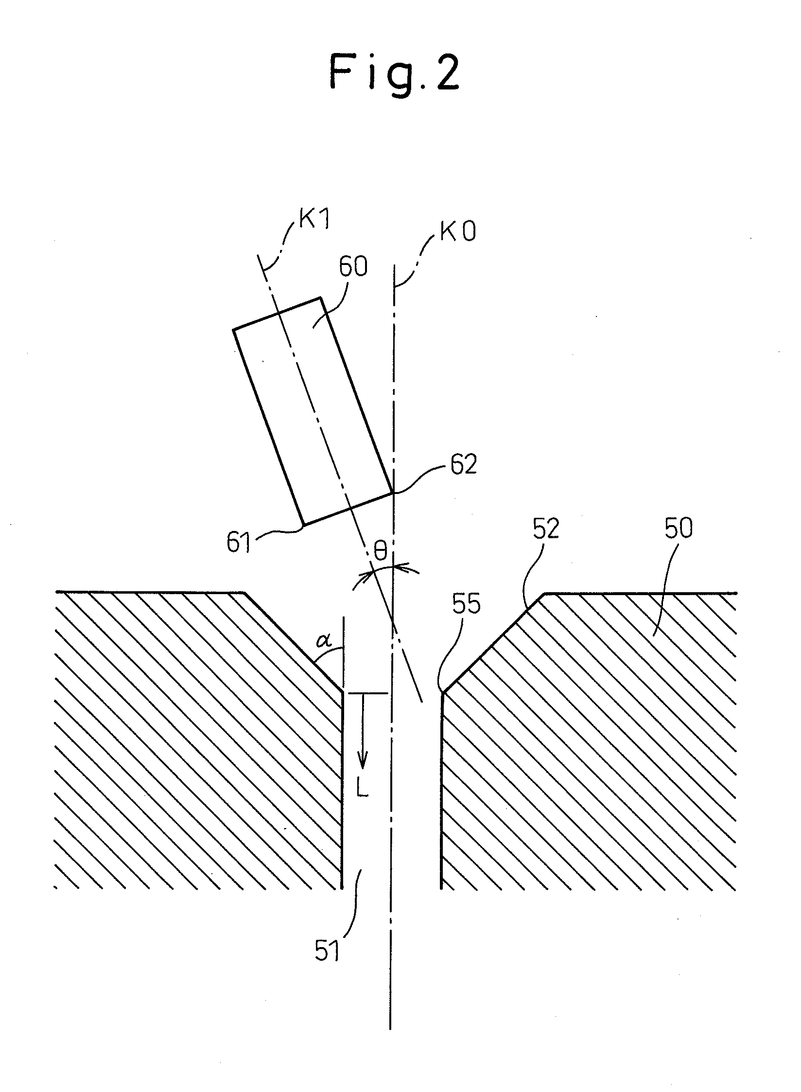
[0015]Specifically, in the first aspect, if the first and second fitting members are in the one-point contact state and in contact with each other at one point, the posture change of the first fitting member is suppressed. As long as the first fitting member is in contact with the second fitting member at one point, the first fitting member does not change from the normal posture. Therefore, during fitting work, the first and second fitting members are not jammed or engaged with each other and the fitting operation can be performed satisfactorily.
[0017]Specifically, in the second aspect, the force or moment can be detected more accurately.

Problems solved by technology

In such a case, after coming into contact at two points, the fitting member 60 may be jammed in the fitting hole 51 or engaged on the inner surface of the fitting hole 51, often resulting in a fitting operation failure.

Method used


Image

  • Fitting device
  • Fitting device
  • Fitting device

Examples


Embodiment Construction

[0029]An embodiment of the invention will be explained below with reference to the accompanying drawings. In the drawings, similar members are designated by similar reference numerals, respectively. To facilitate understanding, the scale of these drawings has been appropriately changed as required.

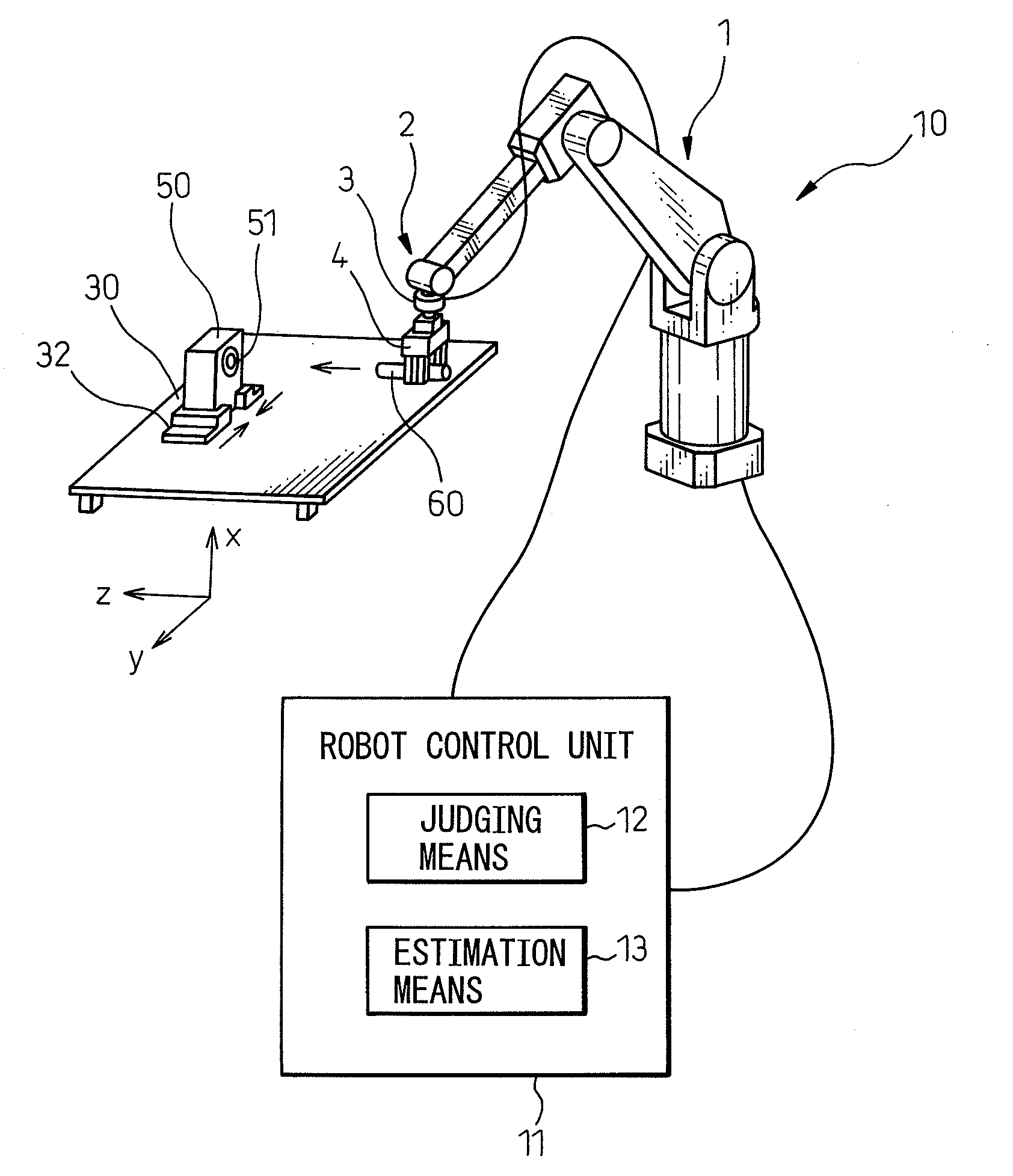
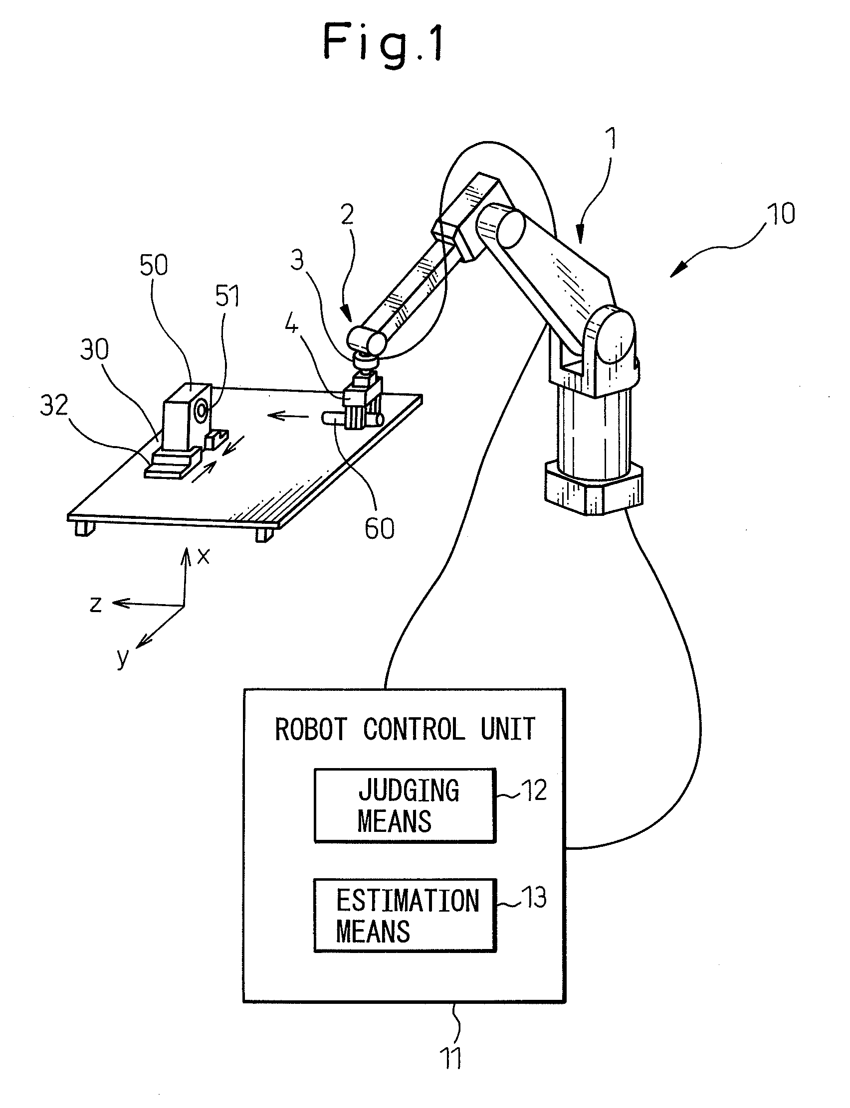
[0030]FIG. 1 is a schematic diagram showing a fitting device according to the invention. A fitting device 10 shown in FIG. 1 includes a robot 1 and a robot control unit 11. The robot 1 is a six-axis vertical multijoint robot. A hand 4 is mounted at the forward end of the robot arm 2 of the robot 1. As shown, a force sensor 3 is arranged between the robot arm 2 and the hand 4. The force sensor 3 detects the force and / or the moment exerted on the hand 4.

[0031]The robot 1 and the force sensor 3 are connected to the robot control unit 11. The robot control unit 11 is a digital computer for controlling the whole operation of the robot 1 of the fitting device 10. Furthermore, the robot control u...


PUM


Abstract

A fitting device for fitting a first fitting member held in a hand mounted at the forward end of a robot arm to a corresponding second fitting member, comprising a detection unit for detecting the force or moment generated when the first and second fitting members come into contact with each other, and a judging unit for judging, based on the force or moment detected by the detection unit, whether a one-point contact state prevails in which the first and second fitting members are in contact with each other at one point or a two-point contact state prevails in which the first and second fitting members are in contact with each other at least two points. In the one-point contact state, the first fitting member held in the hand is pressed against the second fitting member in the fitting direction thereby to proceed with the fitting operation while maintaining the holding posture of the robot arm. In the two-point contact state, the fitting operation is caused to proceed further while the holding posture of the robot arm is changeable. As a result, the first fitting member can be fitted in the second fitting member while keeping the robot arm in the normal posture.

Description

RELATED APPLICATIONS[0001]The present application is based on, and claims priority from, Japanese Application Number 2007-114256, filed Apr. 24, 2007, the disclosure of which is hereby incorporated by reference herein in its entirety.BACKGROUND OF THE INVENTION[0002]1. Field of the Invention[0003]This invention relates to a fitting device for fitting a fitting member held in a hand mounted at the forward end of a robot arm to another fitting member.[0004]2. Description of the Related Art[0005]A fitting operation has conventionally been conducted using a control rule emulating RCC (remote center compliance) by constructing a virtual compliance. Japanese Examined Patent Publication No. 04-43744 discloses one method of fitting a rod-like fitting member held in a robot hand into a fitting hole of a fitted member.[0006]FIG. 8 is a diagram explaining a conventional fitting operation such as disclosed in “Quasi-static Assembly of Compliantly Supported Rigid Parts” by Daniel E. Whitney, Tra...

Claims


Application Information

Patent Timeline
IPC IPC(8): B25J19/00
CPCB25J9/1687G05B2219/39529G05B2219/40032G05B2219/42123
Inventor HATANAKA, KOKOROSATO, TAKASHI
Owner FANUC LTD
Learn More