Methods and systems to facilitate operating within flame-holding margin

Inactive Publication Date: 2008-10-30
GENERAL ELECTRIC CO
View PDF19 Cites 20 Cited by
  • Summary
  • Abstract
  • Description
  • Claims
  • Application Information

AI Technical Summary

Benefits of technology

[0005]In one embodiment, a method to facilitate operating within flame-holding margins in a turbine engine is provided. The method includes coupling at least one turbine nozzle segment within the turbine engine, wherein the at least one turbine nozzle segment includes at least one vane extending between an inner band and an outer band. The method also includes positioning at least one fuel injection orifice in a surface of the at least one vane, channeling a fuel through the at least one fuel injection orifice into a compressed fluid flow to establish a jet penetration height, and defining an operating window by adjusting an operating parameter of the fuel to reduce the jet penetration height and to facilitate increasing the flame-holding margins.
[0006]In another exemplary embodiment, a system to facilita

Problems solved by technology

However, as the cost of gaseous fuels has increased, while gas fuel supplies have become more difficult to secure, at least some known turbines have had to operate with alternative fuels.
Using these methods with non-design gas fuels may decrease the fuel nozzle's flame-holding margins below the desired allowable

Method used


Image

  • Methods and systems to facilitate operating within flame-holding margin
  • Methods and systems to facilitate operating within flame-holding margin
  • Methods and systems to facilitate operating within flame-holding margin

Examples


Example

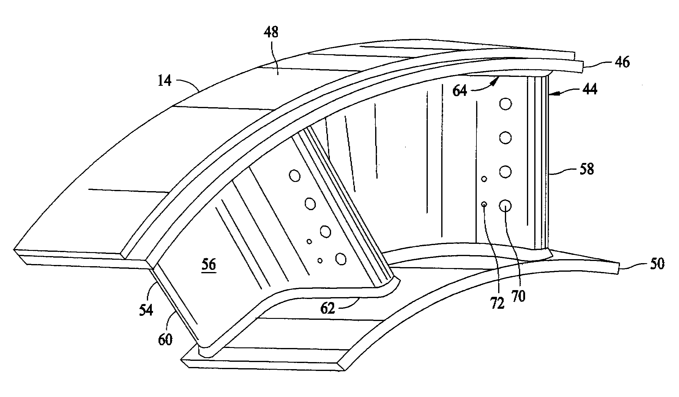
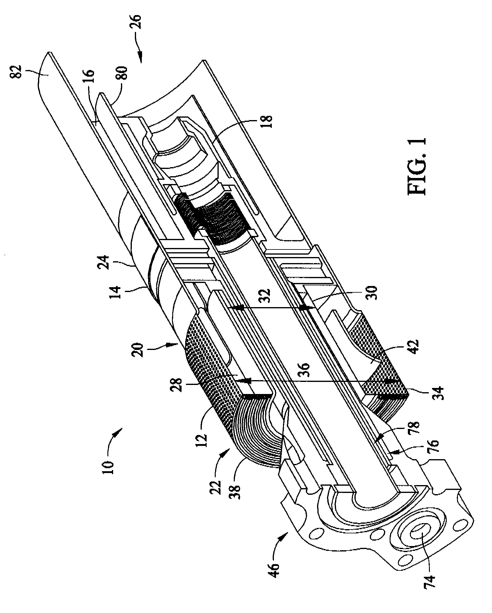
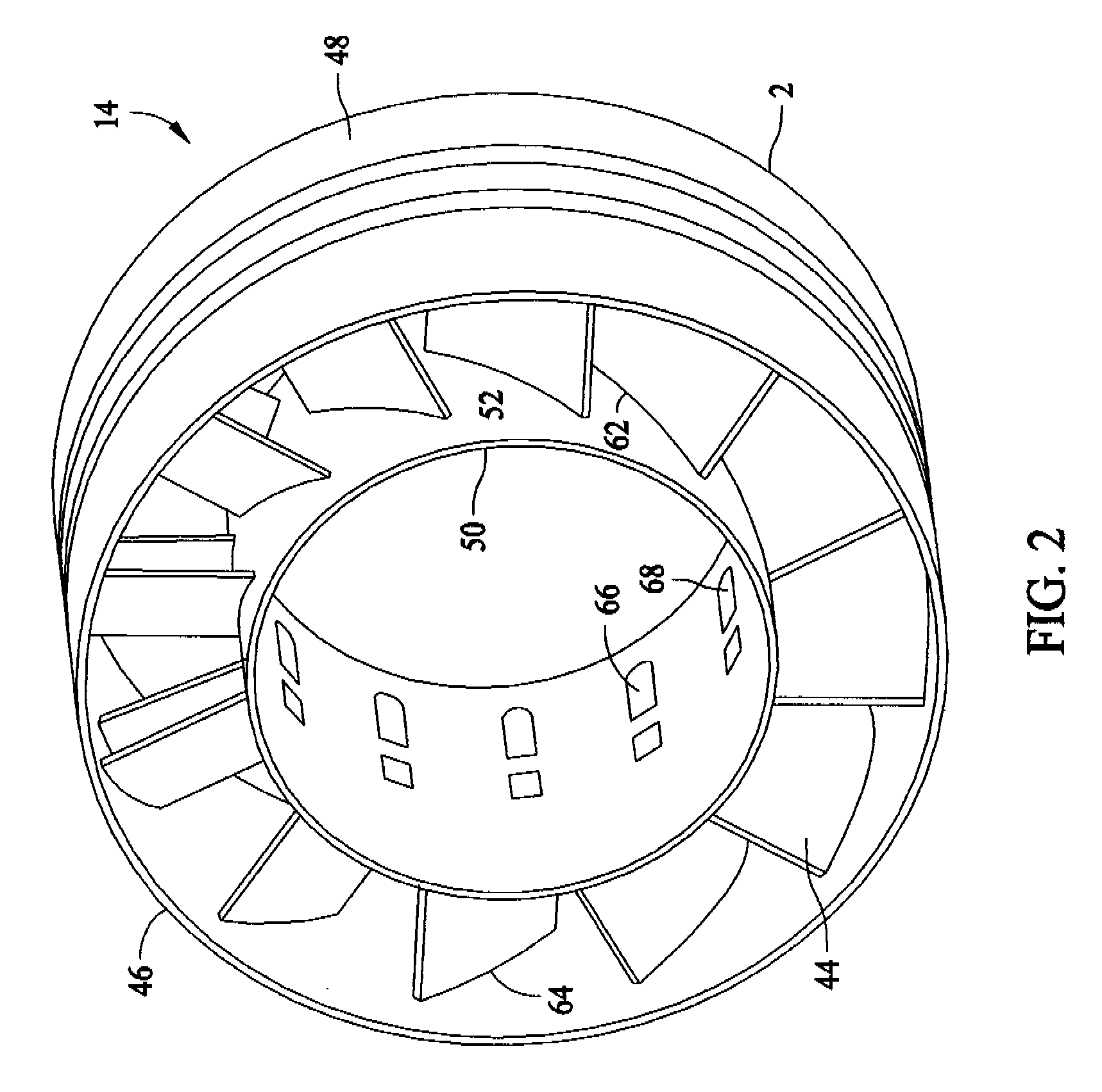
[0014]FIG. 1 is a cross-sectional view of an exemplary nozzle assembly 10. In the exemplary embodiment, nozzle assembly 10 is divided into four regions by function including an inlet flow conditioner (IFC) 12, a swirler assembly 14 with fuel injection, an annular fuel fluid mixing passage 16, and a central diffusion flame fuel nozzle assembly 18. Nozzle assembly 10 also includes a high pressure plenum 20 having an inlet end 22 and a discharge end 24. High pressure plenum 20 circumscribes nozzle assembly 10. Discharge end 24 does not circumscribe nozzle assembly 10, but rather discharge end 24 extends into a combustor reaction zone 26. IFC 12 includes an annular flow passage 28 that is defined by a solid cylindrical wall 30. Wall 30 defines an inside diameter 32 for passage 28, and a perforated cylindrical outer wall 34 defines an outside diameter 36. A perforated end cap 38 is coupled to an upstream end 40 of nozzle assembly 10. In the exemplary embodiment, flow passage 28 includes ...


PUM


Abstract

A method to facilitate controlling flame-holding margins in a turbine engine is provided. The method includes coupling at least one turbine nozzle segment within the turbine engine, wherein the at least one turbine nozzle segment includes at least one vane extending between an inner band and an outer band. The method also includes positioning at least one fuel injection orifice in a surface of the at least one vane, channeling a fuel through the at least one fuel injection orifice into a compressed fluid flow to establish a jet penetration height, and defining an operating window by adjusting an operating parameter of the fuel to reduce the jet penetration height and to facilitate reducing the flame-holding margins.

Description

BACKGROUND OF THE INVENTION[0001]This invention relates generally to turbine assemblies, and more particularly, to methods and systems to facilitate controlling flame-holding margins during turbine operation.[0002]Generally, turbine assemblies used in power generation systems are designed for use with a particular fuel. More specifically, known turbines are designed to achieve mandated nitrous oxide (NOx) emission levels when operating. However, as the cost of gaseous fuels has increased, while gas fuel supplies have become more difficult to secure, at least some known turbines have had to operate with alternative fuels.[0003]At least some known methods of operating turbine assemblies economize fuel consumption by increasing the temperature of the fuel supplied to the turbines using waste heat. By increasing the temperature of the fuel supplied to the turbine, less energy is required to bring the fuel to a turbine operating temperature. For example, in a turbine having an operating ...

Claims


Application Information

Patent Timeline
IPC IPC(8): F01D5/18
CPCF23R3/14F23R3/286F02C9/40
Inventor KRAEMER, GILBERT OTTOLACY, BENJAMIN PAULVARATHARAJAN, BALACHANDARYILMAZ, ERTAN
Owner GENERAL ELECTRIC CO
Why Eureka
Try Eureka