Solenoid pump

a solenoid pump and solenoid technology, applied in the direction of pump control, positive displacement liquid engine, motor parameter, etc., can solve the problems of premature fatigue, wear and failure of the pump,

Inactive Publication Date: 2008-10-30
JOHNSON ELECTRIC SA
View PDF5 Cites 23 Cited by
  • Summary
  • Abstract
  • Description
  • Claims
  • Application Information

AI Technical Summary

Benefits of technology

[0008]providing an electric circuit to energize electro-motion means of the solenoid pump, the electric circuit energizing the electro-motion means with an increased frequency of n times normal mains electricity frequency.

Problems solved by technology

However, vibration caused by the unbalanced movement of the mass of the plunger, and consequently noise associated therewith, is undesirable and can result in premature fatigue, wear and failure of the pump.

Method used


Image

  • Solenoid pump
  • Solenoid pump
  • Solenoid pump

Examples


Embodiment Construction

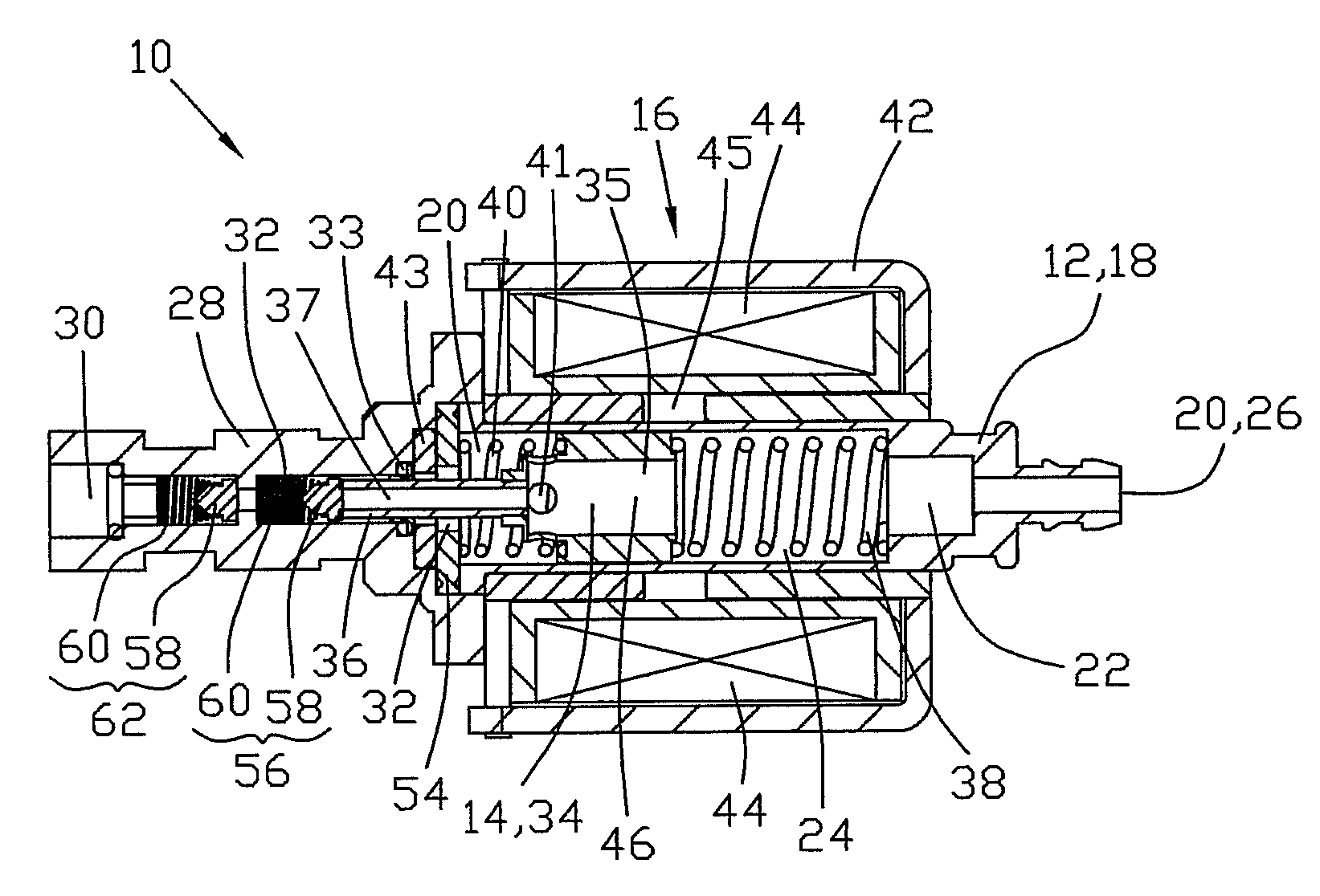
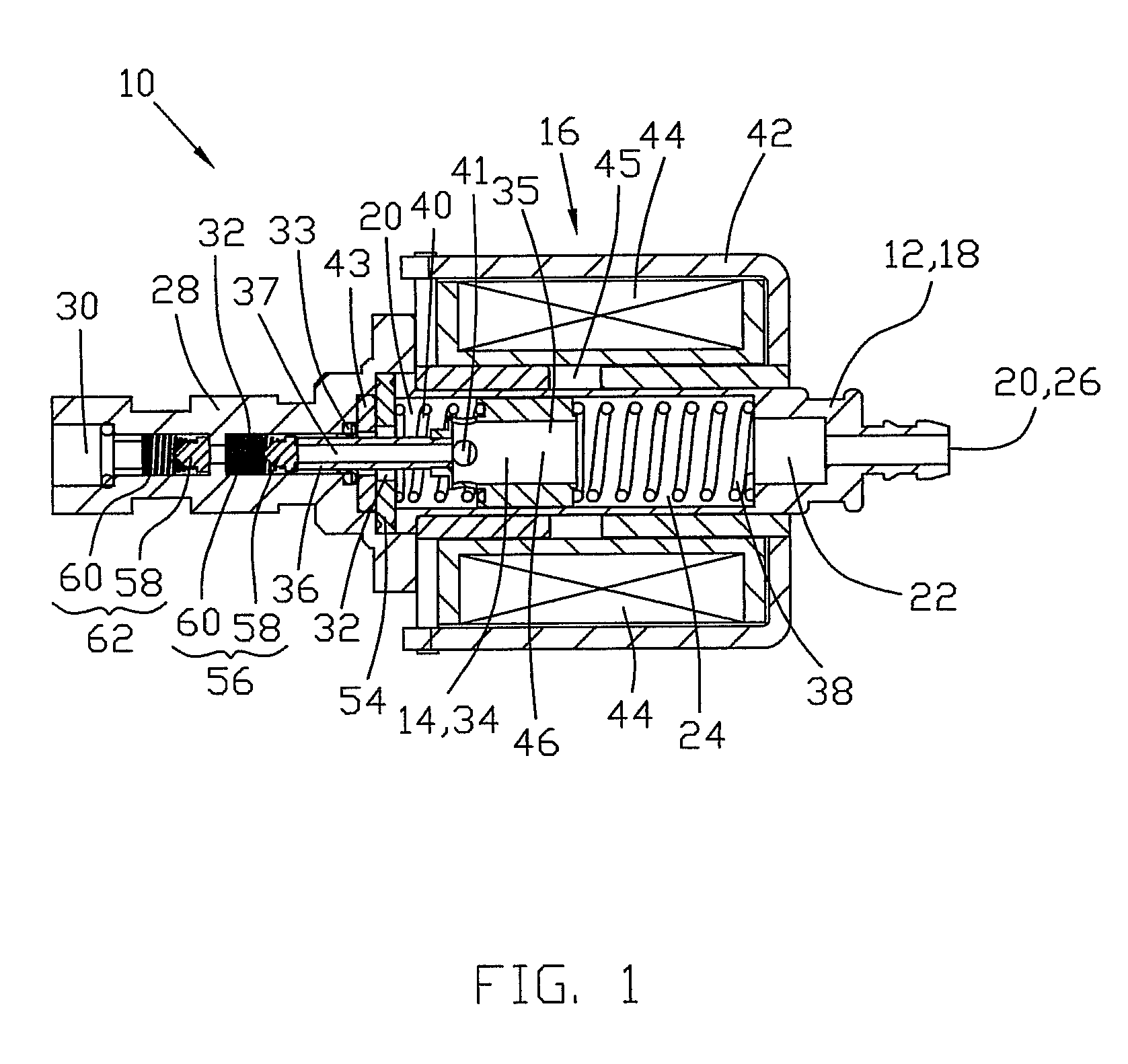
[0025]Referring firstly to FIG. 1 of the drawings, there is shown a solenoid pump 10 which comprises a pump housing 12, a linear reciprocatable plunger 14, and electro-motion means 16 for moving the plunger 14 in a reciprocating manner. The electro-motion means is preferably, in the form of a solenoid.

[0026]The pump housing 12 includes a hollow housing body 18 having two open ends 20 and a stepped-bore 22 therethrough. A plunger chamber 24 is provided within the housing body 18 and is defined primarily by the stepped-bore 22. A first one of the open ends 20 of the housing body 18 forms a liquid inlet port 26 for liquid flow into the plunger chamber 24, and an end cap 28 is fastened, typically by bolts, to the housing body 18 to close a second one of the open ends 20.

[0027]The end cap 28 includes a central rectilinear liquid-outlet passage 30 therethrough. The liquid-outlet passage defines a pump chamber 32 leading from the plunger chamber 24. The plunger chamber 24 is cylindrical an...


PUM


Abstract

A method of reducing or eliminating vibration in a linear reciprocating solenoid pump 10, the method comprising the steps of providing a solenoid pump 10 having a linear reciprocating plunger 14 and providing an electric circuit 48 to energize electro-motion means 16 of the solenoid pump 10, the electric circuit 48 energizing the electro-motion means 16 with an increased frequency of n times the frequency of normal mains electricity.

Description

CROSS-REFERENCE TO RELATED APPLICATIONS [0001]This non-provisional patent application claims priority under 35 U.S.C. §119(a) from Patent Application No. 200710100946.5 filed in China on 28 Apr. 2007.BACKGROUND OF THE INVENTION [0002]This invention relates to solenoid pumps and more particularly to reducing or eliminating vibration and / or noise caused during operation.[0003]Solenoid pumps are well known, and typically comprise a pump housing and a linear reciprocating plunger slidable therein to pump liquid between an inlet and an outlet.[0004]However, vibration caused by the unbalanced movement of the mass of the plunger, and consequently noise associated therewith, is undesirable and can result in premature fatigue, wear and failure of the pump.[0005]The present invention seeks to overcome or mitigate this problem.SUMMARY OF THE INVENTION [0006]According to a first aspect of the invention, there is provided a method of reducing or eliminating vibration in a linear reciprocating so...

Claims


Application Information

Patent Timeline
Patent Type & Authority Applications(United States)
IPC IPC(8): F04B17/04
CPCF04B35/045F04B39/0027F04B49/06F04B49/20F04B2203/0404F04B2203/0406
Inventor LIU, BAO TINGZHANG, GUO JI
Owner JOHNSON ELECTRIC SA
Why Eureka
Try Eureka