
Differential Archwire

a different type of wire technology, applied in the field of different types of wires, can solve the problems of large space between small cross-sectional wires, interfere with the user's bite, and generate too much friction on the slots of posterior teeth brackets, etc., and achieve the effect of eliminating the risk of wire indentations, less pressure, and less pressure on the wir

Inactive Publication Date: 2008-10-30
CANTARELLA DANIELE
View PDF3 Cites 34 Cited by
  • Summary
  • Abstract
  • Description
  • Claims
  • Application Information

AI Technical Summary

Benefits of technology

[0027]One feature of a most preferred embodiment of the present invention is that a rectangular cross sectional area archwire is used wherein the width dimension of the cross sectional areas of each of the anterior portion, first posterior portion and second posterior portion is greater than the height dimension of the corresponding anterior portion, first posterior portion and second posterior portion. Such a rectangular longer width configuration has several advantages. First, the forces that are utilized to close the spaces present in the dental arch are exerted over a semicircle. Hence, these forces have a centripetal component, and they tend to push the teeth towards the side of the tongue and to generate a decrease of the transverse diameter of the dental arches. The component that resists these centripetal forces is given by the rigidity of the archwire along the horizontal plane.
[0028]For this reason it is preferable to use an archwire with rectangular cross-section with the long side of the rectangle parallel to the horizontal plane. This shape of the cross-section of the archwire guarantees a higher rigidity of the archwire along the horizontal plane (better than the round cross-section), and helps to maintain a correct transverse dimension of the dental arch during incisor retraction, and space closure in general.
[0029]Also, en-masse retraction of incisors-canines with the use of mini-screws generates rotational moments that tend to push the upper molars towards the side of the palate, creating a lateral cross-bite. Rectangular cross-section guarantees a higher rigidity of the archwire along the horizontal plane (better than the round cross-section), and helps to maintain a correct transverse dimension of the dental arch.
[0032]As shown in FIG. 32B, with the rectangular cross-section shape (long side of rectangle parallel to horizontal plane) the force is applied over a larger surface (the mesio-buccal width of the rectangle) resulting in less pressure. The many small vertical arrows indicate that the same upwardly directed force (as is represented by the large arrow in FIG. 32A) is distributed over a larger surface, making pressure on the wire much lower hence eliminating the risk of wire indentations.
[0033]A third advantage relates to ease of insertion into a bracket slot. The Conventional combination archwire uses a 021×025 anterior segment, and a 0.021 round in the posterior segment. 021 as vertical dimension has only 001 clearance in the vertical plane. By contrast, an 018×022 posterior portion used in the present invention has 004 of clearance in vertical plane. The larger clearance (004) in the vertical plane of the 018×022 wire makes it easier to insert the archwire than the 021 (clearance001) round wire, when 2nd order bends are present.

Problems solved by technology

In fact, small cross sectional wires often have too much space (play) within the slot and are free to rotate inside the slots of the brackets of the incisors.
Such rotational movement of the incisors is usually not desired, since it results in the lower portions of the upper incisors contacting the lower incisors, which thereby interferes with the user's bite.
However, it generates too much friction on the slots of the brackets of the posterior teeth, hampering the sliding of the archwire along the brackets of posterior teeth.
The main drawback of the “bi-dimensional technique” is that the thickness of the archwire that can be utilized is limited to a cross-sectional size of 0.018 by 0.022 inches (0.45720 by 0.55880 mm).
This limitation exists because the archwire must fit into slots of the brackets of the incisors that have a height of 0.018 inches (0.45720 mm).
Unfortunately, an archwire of such limited size cannot control the bucco-lingual inclination (torque) of the posterior teeth (canines, premolars, molars), which is important in other phases of the orthodontic treatment (for example during the repositioning of impacted canines or during the up-righting of linguo-inclined molars).
One drawback of Wool's archwire design is that the flexural rigidity of anterior and posterior segments is the same.
The main drawback of the loerster design is that the anterior segment that is composed of a super-elastic material, does not generate enough rigidity of the archwire along the horizontal plane.
As a consequence, the forces used to move the teeth backwards cause a rotational pivoting of the teeth towards the side of the tongue, rather than the desired translational movement of the teeth.
The drawback of the round cross-section shape is that it doesn't generate enough rigidity of the wire along the horizontal plane.
The problems associated with the closing loops are that the loops can irritate the cheeks and that they tend to trap food and plaque.
Furthermore, the activation of the loops and the removal of the archwire require a procedure that consumes a large amount of the dentist's time, as the archwire must be either cut or “unbent” in order to be removed.

Method used


Image

  • Differential Archwire
  • Differential Archwire
  • Differential Archwire

Examples


first embodiment

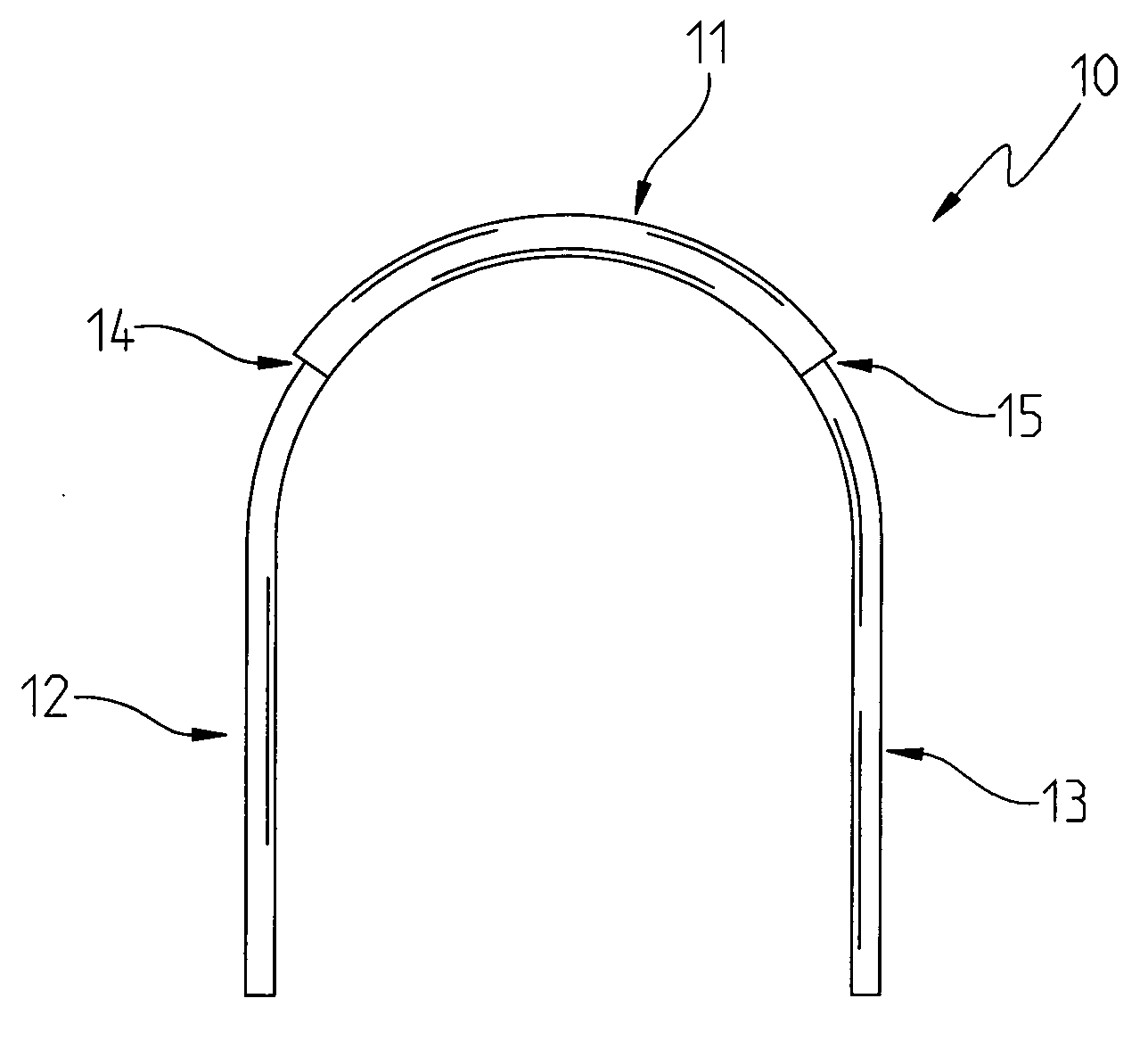
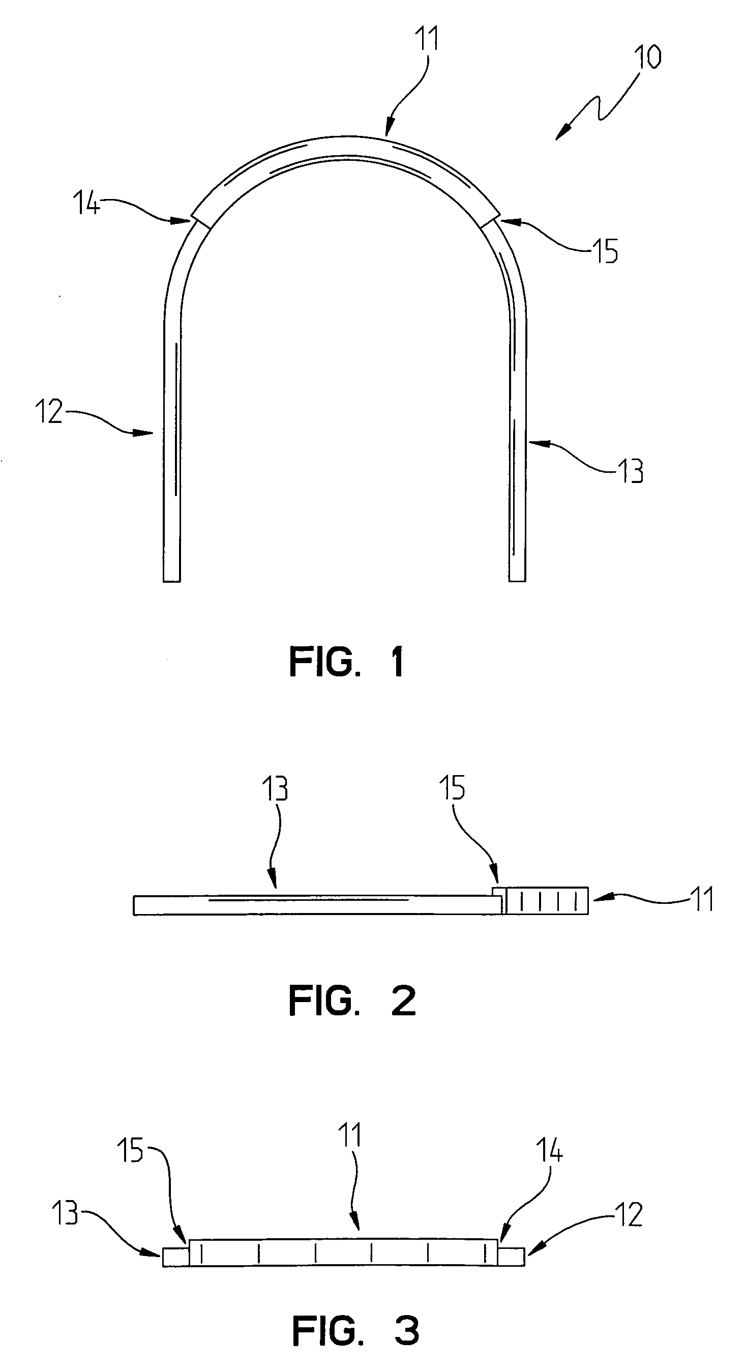
[0075]As best shown in FIG. 1, the differential archwire 10 of the present invention is shown as including an anterior portion 11, a first posterior portion 12, and a second posterior portion 13. When inserted in the mouth, the anterior portion 11 is disposed adjacent to the anterior teeth, such as the central and lateral incisors. The first 12 and second 13 posterior portions are disposed adjacent to the posterior teeth, such as the canines, the first and second bi-cuspids (first and second pre-molars), and the first, second and third molars.

[0076]If one views the dental archwire 10 from the top, as shown in the top view of FIG. 1, the first posterior portion 12 will be inserted into the left portion of the mouth, and that the second posterior portion 13 of the dental archwire 10 will be disposed in the right portion of the mouth.

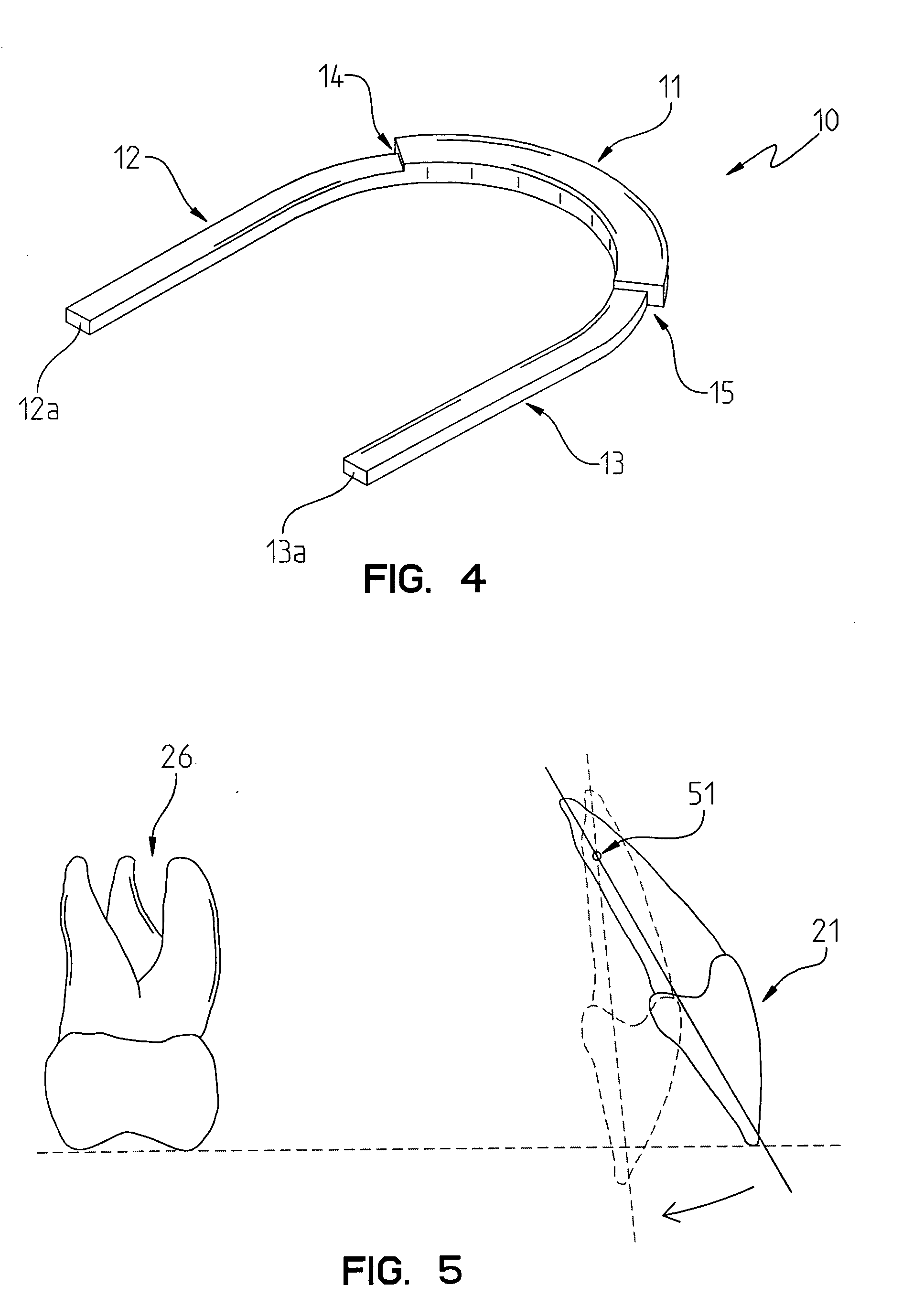
[0077]As will be observed from the drawings in FIGS. 1-4, the anterior portion 11 is generally thicker than the posterior portions 12, 13. Another way to ...

embodiment 300

[0113]In the embodiment 300 of differential archwire 300 shown in FIG. 16-31, for the same amount of linear deflection of the wire (f in the above formula) and for the same length of wire (L in the above formula), the posterior segments (18×22) generate a force response that is 45% less than the force response generated by the anterior segment 311 (21×25) due to the differences in cross-section sizes of the segments 312, 313, 311.

[0114]The force response of a deflected orthodontic wire acts at the wire-bracket interface. More precisely, during incisor retraction, this force response of the deflected wire is exerted in a perpendicular fashion (normally) to the direction of backward sliding of the wire through the brackets. The direction of the force response of the deflected wire is indicated generally by arrows 74A, 70A, 66A and 62A shown in FIG. 31. So, the force response of the deflected wire produces friction, that hampers the backward movement of the wire (and of incisors).

[0115...

embodiment 310

[0131]The plane in which the anterior segment 311 resides is disposed generally above the level of the plane in which the posterior segments 312, 313 reside. Rather than using a bend to differentiate the level between the anterior section 311 and posterior section 312, 313, in the embodiment 310 shown in FIG. 17, the non-coplanarity is achieved by attaching the underside surface of the posterior end portions 323, 325 of the anterior segment 311 to the upper side surfaces of the proximal end portion 322, 324 of the respective posterior segments 312, 313. This overlayed transition section 314, 315, as described above, is an area where the thickness of the archwire, due to the combined cross-sectional areas of the anterior segment 311 and posterior segment 312, 313 is greater than in any other place within the archwire. This results in the transition area 314, 315 having the highest flexural rigidity of any portion of the archwire 310.

[0132]An alternate and preferred embodiment archwir...


PUM


Abstract

An archwire is disclosed for use in an orthodontic appliance of the type that includes brackets attached to a surface of at least one tooth. The archwire includes an anterior portion for engaging at least one bracket of at least one anteriorly disposed tooth in a patient's mouth. The anterior portion includes a relatively larger cross sectional area, a first end portion and a second end portion. A first posterior portion is provided for engaging at least one bracket of at least one posteriorly disposed tooth in a patient's mouth. The first posterior portion includes a proximal end portion fixedly coupled to the first end portion of the anterior portion, and a second end. A second posterior portion is provided for engaging at least one bracket of at least one posteriorly disposed tooth in a patient's mouth. The second posterior portion includes a proximal end portion fixedly coupled to the second end portion of the anterior portion of the second end. The first and second posterior portions each have a relatively smaller cross sectional area than the relatively larger cross sectional area of the anterior portion.

Description

REFERENCE TO RELATED APPLICATIONS[0001]This application is a continuation-in-part of International Application No. PCT / IT2006 / 000803, filed 17 Nov. 2006; this application claims priority to International Application No. PCT / IT2006 / 000803, filed 17 Nov. 2006 which itself claims priority to Italian Patent Application No. TV2005A000194, filed 12 Dec. 2005 both of which are incorporated fully herein by reference.[0002]I. Technical Field of the Invention[0003]The present invention relates to orthodontic appliances, and more particularly to an archwire to be utilized as a component of fixed orthodontic appliances.[0004]II. Background of the Invention[0005]It is known that orthodontic appliances are utilized to move teeth along the three planes of the space inside a mouth. Fixed orthodontic appliances include a series of brackets glued to the teeth. Archwires are secured in slots that are usually formed as a part of the brackets. Brackets having slots with a rectangular cross-sectional sha...

Claims


Application Information

Patent Timeline
Patent Type & Authority Applications(United States)
IPC IPC(8): A61C7/20
CPCA61C7/20
Inventor CANTARELLA, DANIELE
Owner CANTARELLA DANIELE
Features
  • Generate Ideas
  • Intellectual Property
  • Life Sciences
  • Materials
  • Tech Scout
  • Unparalleled Data Quality
  • Higher Quality Content
  • 60% Fewer Hallucinations
Learn More