Delayed Base Station Relocation in Distributed Radio Access Networks

a technology of radio access network and delay, applied in the direction of data switching network, digital transmission, electrical apparatus, etc., can solve the problem of time-consuming execution of radio mobility-related procedures, and achieve the effect of minimizing the delay caused by executing radio mobility-related procedures and minimizing the signaling load in the network

Inactive Publication Date: 2008-10-30
PANASONIC CORP
View PDF5 Cites 77 Cited by
  • Summary
  • Abstract
  • Description
  • Claims
  • Application Information

AI Technical Summary

Benefits of technology

[0115]Timely execution of radio mobility-related procedures is a central problem when improving serving network element relocation. Hence, the problem with serving network element relocation in distributed radio access network architecture may be to optimize the relocation procedure such that the delay caused by executing radio mobility-related procedures is minimized. A further constraint of this optimization may be to minimize the signaling load in the network during the relocations that are shown to be much more frequent relative to the legacy architecture.

Problems solved by technology

Timely execution of radio mobility-related procedures is a central problem when improving serving network element relocation.

Method used


Image

  • Delayed Base Station Relocation in Distributed Radio Access Networks
  • Delayed Base Station Relocation in Distributed Radio Access Networks
  • Delayed Base Station Relocation in Distributed Radio Access Networks

Examples


Embodiment Construction

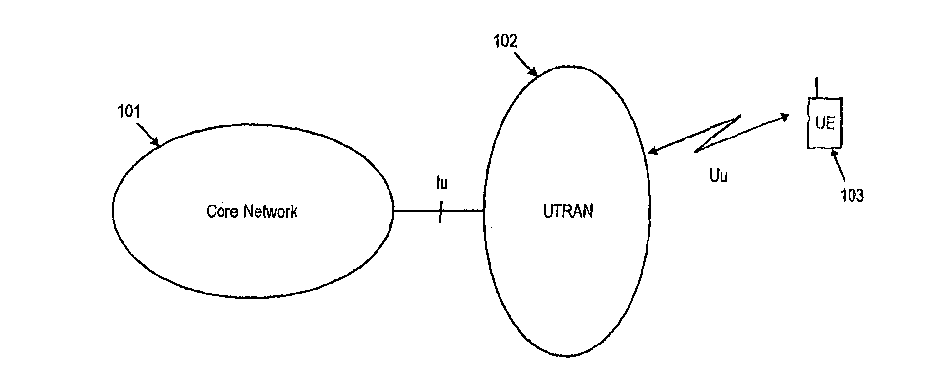
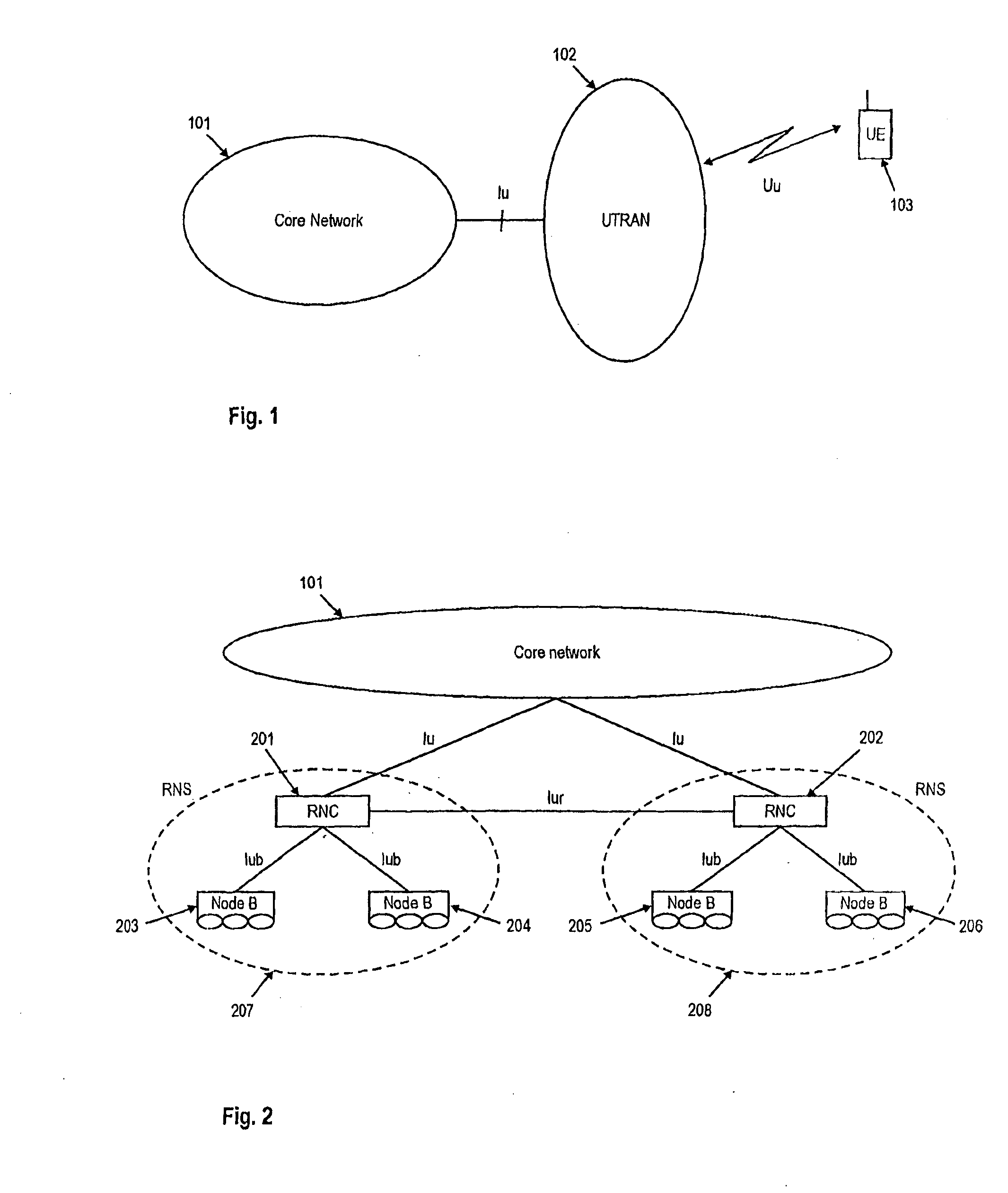
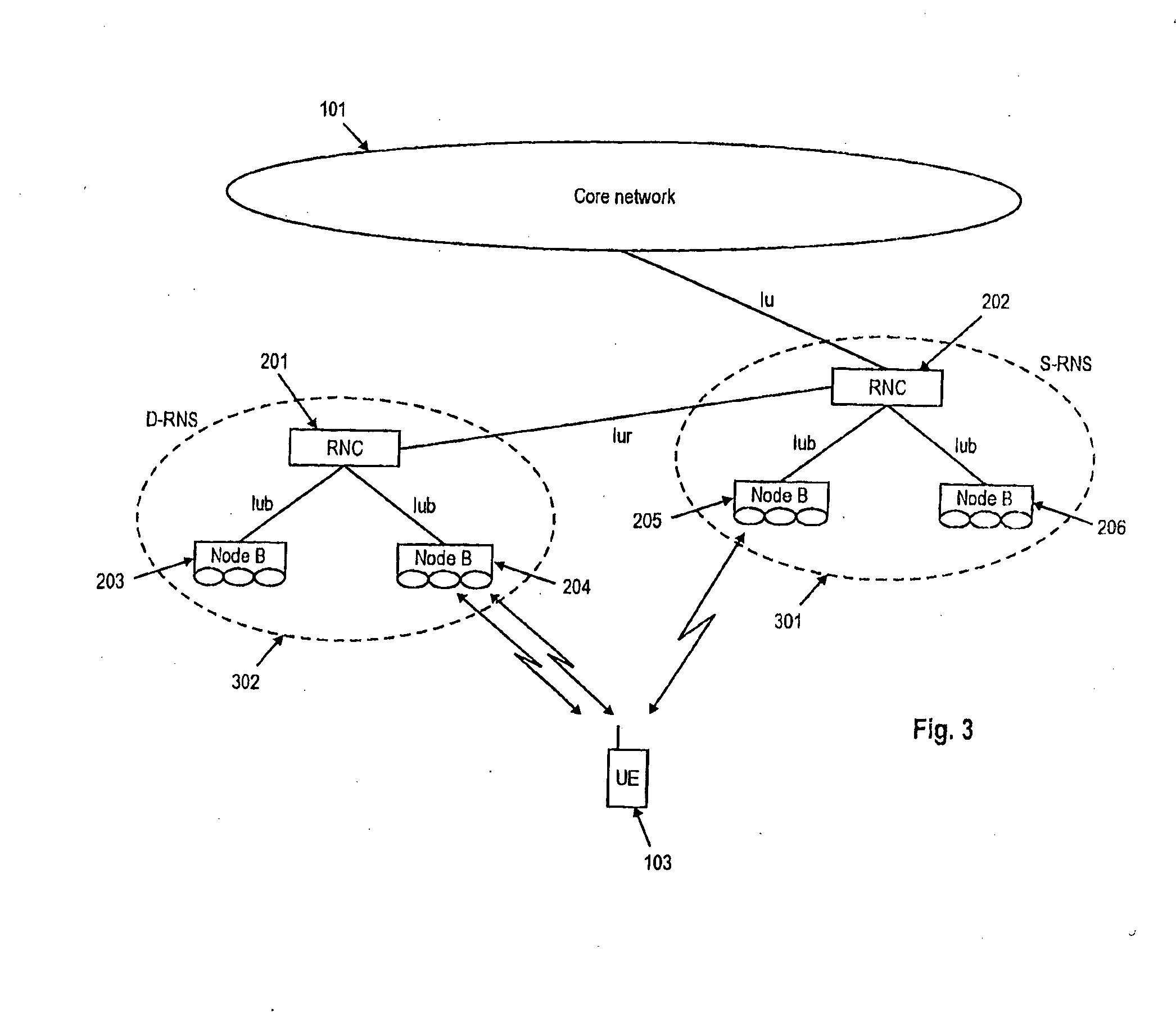
[0168]The following paragraphs will describe various embodiments of the present invention. For exemplary purposes only, most of the embodiments are outlined in relation to a UMTS communication system and the terminology used in the subsequent sections mainly relates to the UMTS terminology. However, the used terminology and the description of the embodiments with respect to an UMTS architecture is not intended to limit the principles and ideas of the present inventions to such systems.

[0169]The additional “+” sign appended to the protocols or network elements are intended to denote that these protocols and network elements may have an enhanced functionality or may be adapted to the Evolved UTRAN architecture. The additional “+” sign should however not be understood as a limitation of the principles and ideas of this invention.

[0170]Also the detailed explanations given in the Technical Background section above are merely intended to better understand the mostly UMTS specific exemplar...


PUM


Abstract

The present invention relates to a method for relocating control plane functionality of a serving base station in a mobile communication system comprising a mobile terminal and a plurality of base stations. Further, the present invention relates to a base station in a mobile communication system and to the mobile communication system. To tackle potentially intolerable delay of control signaling due to frequent serving network element relocations in the network architecture the present invention suggests a partial relocation of a serving network element wherein the control plane functionality is relocated but connection to the core network via a gateway is maintained through the previous serving network element. A further aspect of the present invention suggests a total relocation, where control plane functionalities are relocated and where a new connection to the core network is established between the new serving network element and the gateway. Also decision criteria on whether to perform partial or total relocation are provided.

Description

FIELD OF THE INVENTION[0001]The present invention relates to a method for relocating control plane functionality of a serving base station in a mobile communication system comprising a mobile terminal and a plurality of base stations. Further, the present invention relates to a base station in a mobile communication system and to the mobile communication system.TECHNICAL BACKGROUND[0002]W-CDMA (Wideband Code Division Multiple Access) is a radio interface for IMT-2000 (International Mobile Communication), which was standardized for use as the 3rd generation wireless mobile telecommunication system. It provides a variety of services such as voice services and multimedia mobile communication services in a flexible and efficient way. The standardization bodies in Japan, Europe, USA, and other countries have jointly organized a project called the 3rd Generation Partnership Project (3GPP) to produce common radio interface specifications for W-CDMA.[0003]The standardized European version o...

Claims


Application Information

Patent Timeline
Patent Type & Authority Applications(United States)
IPC IPC(8): H04Q7/20H04L12/56H04W36/06H04W36/10H04W36/18
CPCH04W36/06H04W36/10H04W36/18
Inventor PETROVIC, DRAGANSEIDEL, EIKOLOHR, JOACHIM
Owner PANASONIC CORP
Why Eureka
Try Eureka