Embolectomy device

a technology of embolectomy and proximal tube, which is applied in the field of intravascular devices, can solve the problems of not always practical or desirabl

Inactive Publication Date: 2008-10-30
STRYKER EURO OPERATIONS HLDG LLC +1
View PDF59 Cites 65 Cited by
  • Summary
  • Abstract
  • Description
  • Claims
  • Application Information

AI Technical Summary

Problems solved by technology

If an embolus is not removed it may travel to the neural vasculature, for example, and cause severe trauma.
This is not always practical or desirable.
This may cause the collapse of a portion of the vasculature and result in trauma.

Method used


Image

  • Embolectomy device
  • Embolectomy device
  • Embolectomy device

Examples


Embodiment Construction

[0017]The following detailed description should be read with reference to the drawings, in which like elements in different drawings are numbered identically. The drawings which are not necessarily to scale, depict selected embodiments and are not intended to limit the scope of the invention.

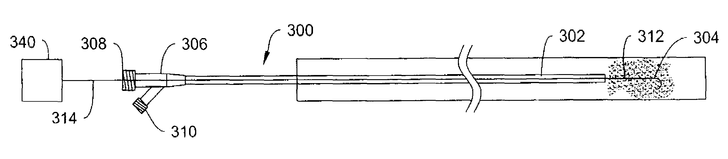
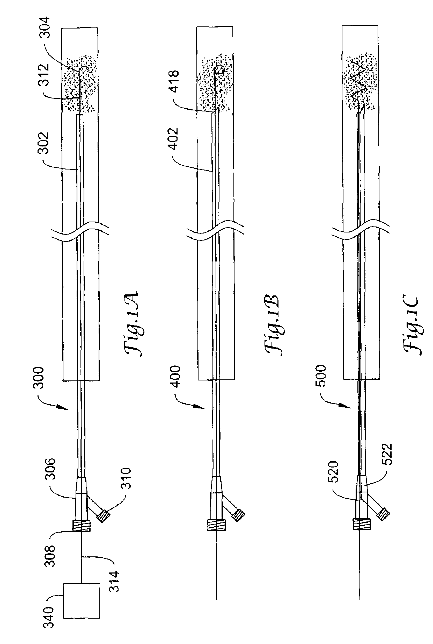
[0018]FIG. 1a depicts an embolectomy device 300 disposed in a body lumen. Device 300 includes catheter 302 and distal device 304. Distal device 304 may be used to unclog the aspiration lumen or to fragment an embolus for aspiration. Catheter 302 may have a manifold 306 attached proximally including a first port 308 and a second port 310. Distal device 304 has a proximal end 312 attached to an elongate member 314 disposed in a lumen of catheter 302. Distal device 304 may have an arcuate shape, or may be formed into a loop, coil, paddle, whisk, zigzag, helical or other shape suitable for fragmenting an embolus. The proximal end of elongate member 314 may be free or may be attached to a motion cont...


PUM


Abstract

An embodiment is a catheter comprising a first elongate shaft having a proximal end, a distal end and a first lumen therethrough, a wire having a proximal end and a distal end at least partially disposed in the first elongate shaft, the distal end extending distally from the first elongate shaft, and a motion control apparatus connected to the proximal end of the wire, further comprising a device attached to the distal end of the wire for changing the shape of an embolus, wherein the device is configured to change the shape of the embolus to unclog a distal catheter lumen.

Description

RELATED APPLICATIONS[0001]This application is a divisional application of U.S. patent application Ser. No. 10 / 664,134 filed Sep. 17, 2003.FIELD OF THE INVENTION[0002]The present invention relates generally to the field of intravascular devices. More specifically, the present invention pertains to embolectomy devices for aspirating foreign bodies within a body lumen.BACKGROUND OF THE INVENTION[0003]There are a number of situations in the practice of medicine where it is desirable to remove an embolus from a patient's vasculature. If an embolus is not removed it may travel to the neural vasculature, for example, and cause severe trauma. Many prior art embolectomy devices require a retrieval portion to be placed downstream or distal the embolus. This is not always practical or desirable. Other prior art embolectomy devices may require the use of a significant vacuum to remove the embolectomy. This may cause the collapse of a portion of the vasculature and result in trauma.SUMMARY OF TH...

Claims


Application Information

Patent Timeline
Patent Type & Authority Applications(United States)
IPC IPC(8): A61M1/34A61B17/00A61B17/22A61M25/00
CPCA61B17/22012A61B17/221A61B2017/22034A61B2017/2215A61M25/0069A61M2025/0004
Inventor RAMZIPOOR, KAMALNAIR, AJITKUMAR B.PARIKH, RITENHUFFMASTER, ANDREWBASHIRI, MEHRANPHAM, PETE PHONG
Owner STRYKER EURO OPERATIONS HLDG LLC
Why Eureka
Try Eureka