
Multi-directional adjustment hinge

a multi-directional, hinge technology, applied in the field of hinges, can solve the problems of loosening the structure at the place of the adjustment screw, high cost of mold development for those parts, and high cost of assembly process, so as to achieve excellent tension, reduce production cost, and facilitate assembly

Inactive Publication Date: 2008-11-06
KING SLIDE WORKS CO LTD
View PDF12 Cites 30 Cited by
  • Summary
  • Abstract
  • Description
  • Claims
  • Application Information

AI Technical Summary

Benefits of technology

[0006]The primary purpose of the present invention is to provide a multi-directional adjustment hinge to solve the problem of a loosening structure of the hinge adjustment, allow more compact construction of the hinge, and reduce production cost.
[0014]When compared to the prior art, the present invention provides the following effects and advantages:
[0015]a. The extension plate and the locating plate are two key components other than the head plate, the adjustment screw, and the adjustment cam in the present invention allowing easy assembly and lower production cost; and
[0016]b. The extension plate connects the locating plate by means of the inwardly bent joint; and where the connection takes place provides a proper elasticity; and by means of the elasticity, an excellent tension presents at where the adjustment screw connects the extension plate and another end of the locating plate not only to provide a firm connection but also to ensure a longer service life of the hinge by preventing the turning of the adjustment screw from getting too tight.

Problems solved by technology

Other than the head plate, four types of parts (not including adjustment screw or cam) as a minimum are included in the constructional design as disclosed in U.S. Pat. Nos. 6,647,591 B1 and 6,845,544 B2, resulting in higher cost in developing molds for those parts, complicate and tedious assembly process, and the problem of loosening structure at where the adjustment screw is provided after prolonged use.

Method used


Image

  • Multi-directional adjustment hinge
  • Multi-directional adjustment hinge
  • Multi-directional adjustment hinge

Examples


Embodiment Construction

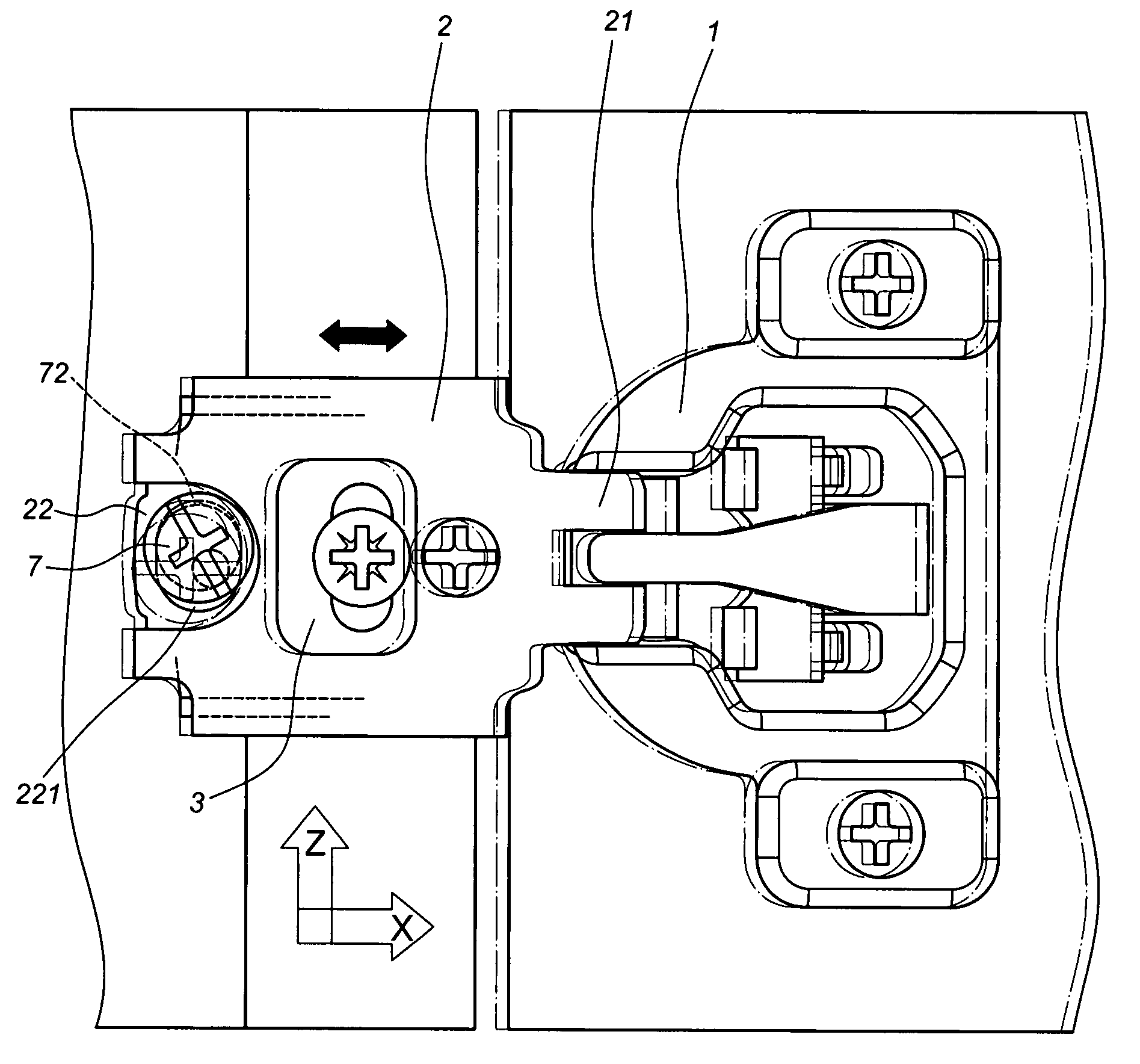
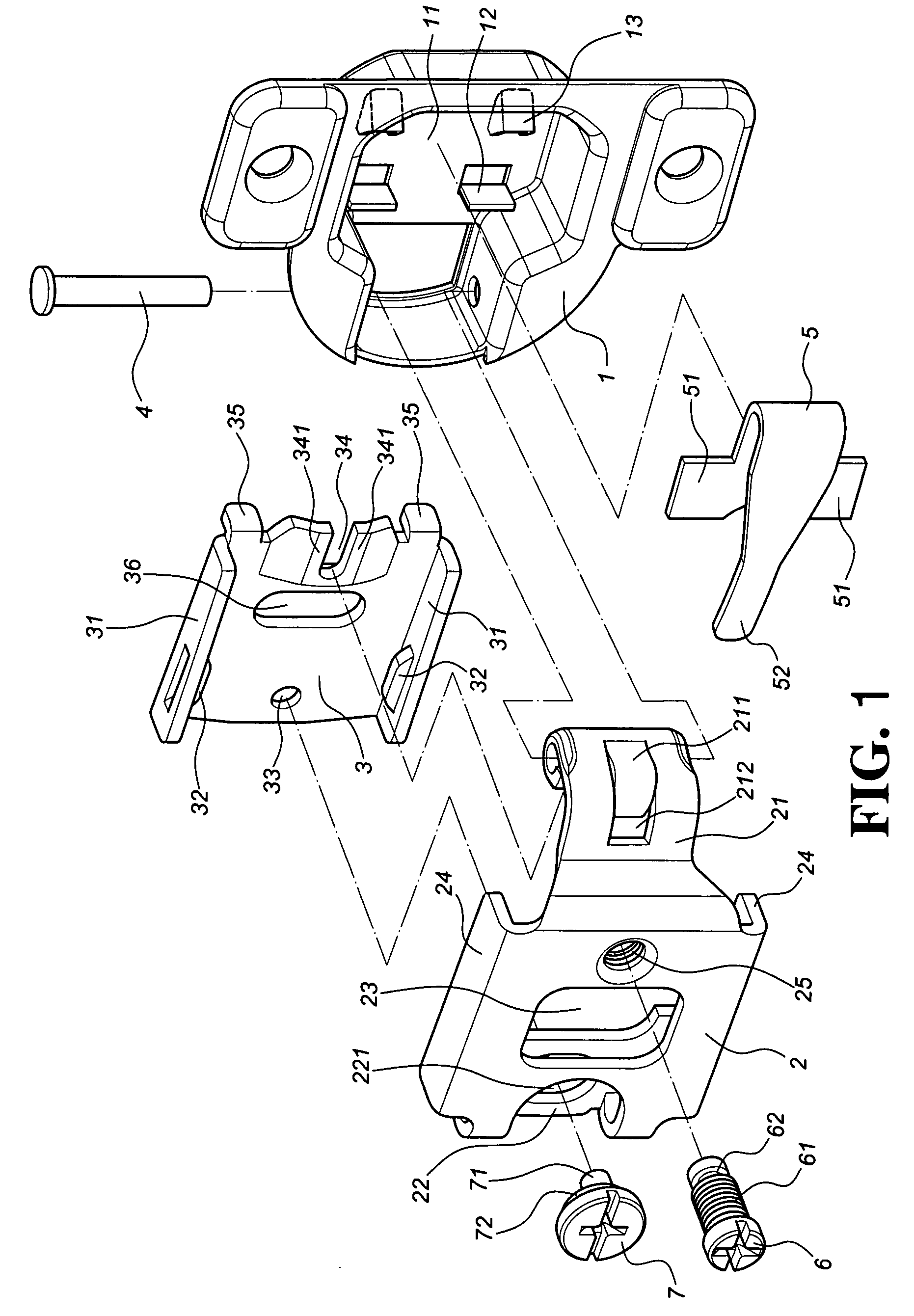
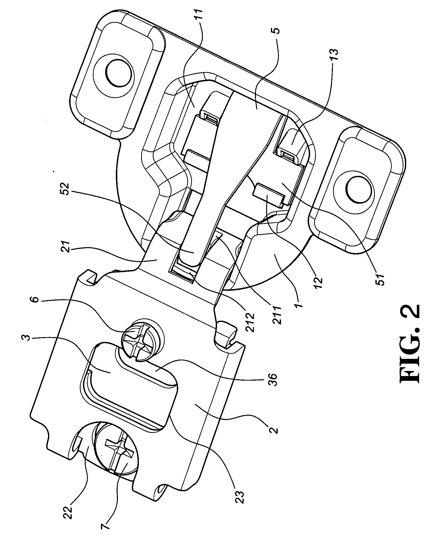
[0024]Referring to FIGS. 1 and 2, a preferred embodiment of the present invention comprises a head plate (1), an extension plate (2), a locating plate (3), a pivot pin (4), a spring tongue (5), an adjustment screw (6), and an adjustment cam (7).

[0025]The head plate (1) contains a chamber (11), and locating pieces (12) and retainers (13) are disposed at the bottom of the chamber (11).

[0026]The extension plate (2), as illustrated in FIG. 3, is a plate provided with two opposite ends. A through hole (23) is disposed at a central portion of the extension plate (2). A pair of sidewalls (24) is provided at both sides of the extension plate (2). An arm (21) extends from one end of the extension plate (2) and a cam portion (211) formed at the end of the arm (21) extends into the chamber (11) of the head plate (1) to be pivoted to the head plate (1). The arm (21) is formed with a slot (212) adjacent to the cam portion (211). A joint (22) inwardly curved is disposed at another end of the exte...


PUM


Abstract

A multi-directional adjustment hinge includes a head plate, an extension plate, a locating plate, a pivot pin, a spring tongue, an adjustment screw, and an adjustment cam. The head plate has a chamber. An arm extends from one end of the extension plate and another end of the extension plate is provided with a joint. A pair of sidewalls is disposed at both sides of the extension plate. Two lips are disposed at both sides of the locating plate to be inserted between the sidewalls and side edges of the joint. Each lip contains a protruding tab to hold against the joint. One side of the extension plate and the locating plate is linked to interact with each other by means of the adjustment screw. Another side of the locating plate and the joint is linked to interact with each other by means of the adjustment cam.

Description

BACKGROUND OF THE INVENTION[0001](a) Field of the Invention[0002]The present invention is related to a hinge, and more particularly, to a multi-directional adjustment hinge comprised of compact components with a more reliably constructed adjustment.[0003](b) Description of the Prior Art[0004]A furniture hinge commonly used to a cabinet is essentially comprised of a head plate, an extension arm, and a locating plate, wherein the extension arm is pivoted to the head plate to become a movable part, the head plate is usually fixed to an object including a door plank, the extension arm is connected to the locating plate secured on the cabinet, and an elastic member disposed in the head plate applies force on the extension arm to deliver a certain closing force when the door plank is pushed back to shut the cabinet.[0005]The furniture hinge is further designed with a multi-directional adjustment in axes X, Y, and Z as taught in U.S. Pat. Nos. 6,470,531 B2, 6,643,895 B1, 6,647,591 B1, 6,69...

Claims


Application Information

Patent Timeline
IPC IPC(8): E05D7/04
CPCE05D7/0407Y10T16/53225E05Y2900/20E05F1/1284
Inventor CHEN, KEN-CHINGLIANG, HSIU-CHIANGWANG, CHUN-CHIANG
Owner KING SLIDE WORKS CO LTD
Learn More