Slip type pipe joint

a pipe joint and axial movement technology, applied in the direction of pipe/joint/fitting, non-disconnectible pipe joints, adjustable joints, etc., can solve the problems of pipe moving axially away, pipe being too short, and difficulties in making repairs and modifications to existing rural piping systems

Inactive Publication Date: 2008-11-06
JTL AUSTRALIA
View PDF14 Cites 13 Cited by
  • Summary
  • Abstract
  • Description
  • Claims
  • Application Information

AI Technical Summary

Problems solved by technology

Difficulties do arise, however, when the pipes are later coupled together and contraction of the pipe has occurred or when inserting the inserts (liners) as this operation can cause the pipes to move axially away from themselves, resulting in the fitting being too short.
Difficulties also arise when making repairs and modifications to existing rural piping systems, particularly where the piping is buried and the ground has become extremely hard to penetrate.
The pipe can also contract when the pipe is cut making the gap too long for a standard single coupling or joiner to be used.
The process of digging to clear around a si

Method used


Image

  • Slip type pipe joint
  • Slip type pipe joint
  • Slip type pipe joint

Examples


Embodiment Construction

[0023]A preferred embodiment of the invention is illustrated in the accompanying representations in which:

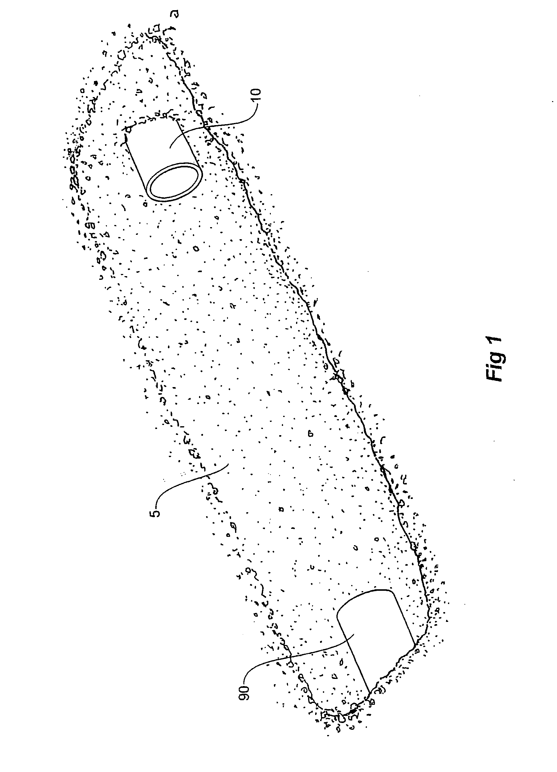
[0024]FIG. 1 shows a trench exposing pipe ends ready to be joined by a pipe fitting.

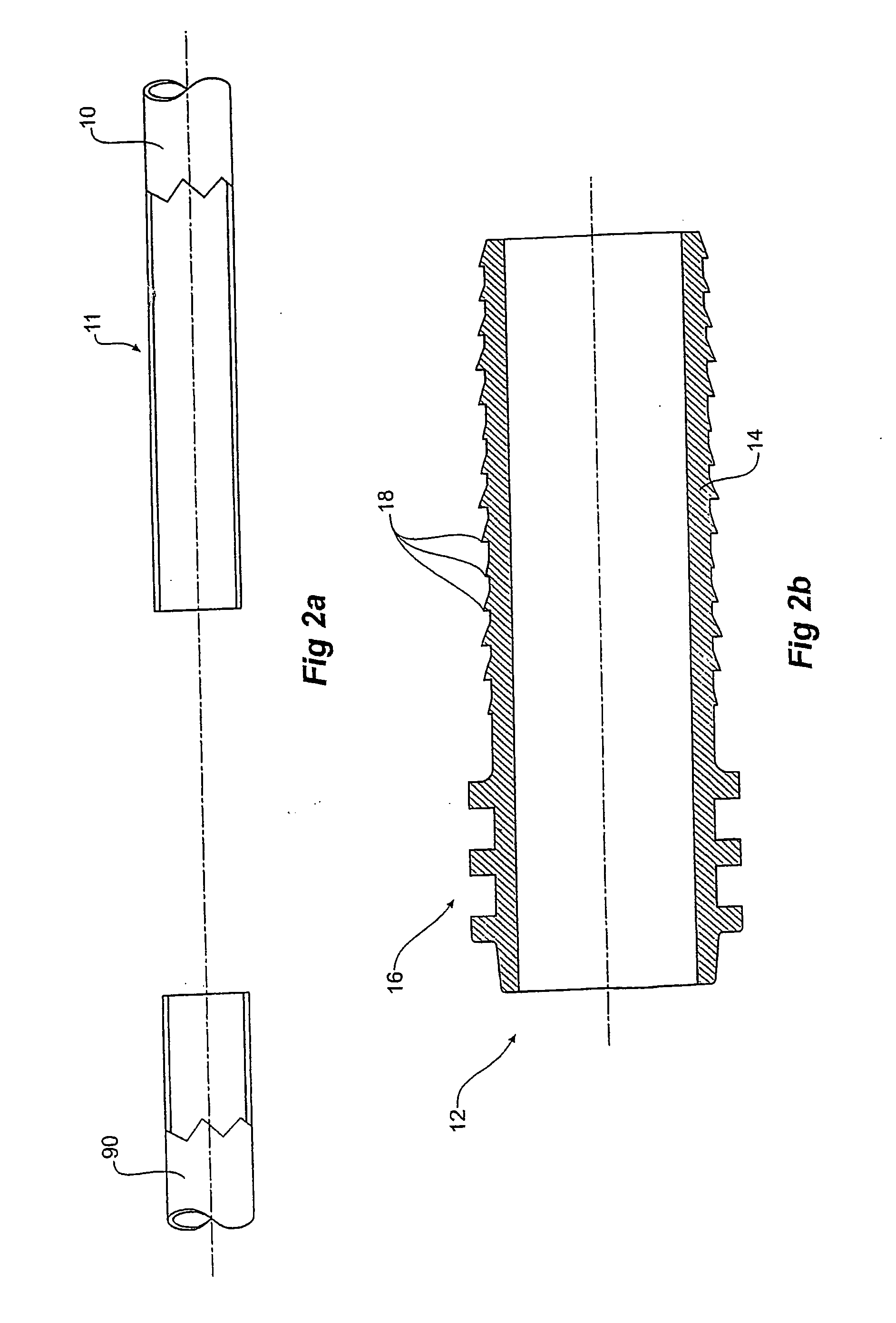
[0025]FIG. 2a shows the pipe ends of FIG. 1 in a cutaway cross-sectional view.

[0026]FIG. 2b shows a cross-sectional view of a first insert for insertion into a pipe end.

[0027]FIG. 3 shows the first insert of FIG. 2b and a second insert inserted into the pipe ends of FIG. 1 and FIG. 2a.

[0028]FIGS. 4 and 5 show a slip type pipe joint according to the invention in progressive stages of assembly.

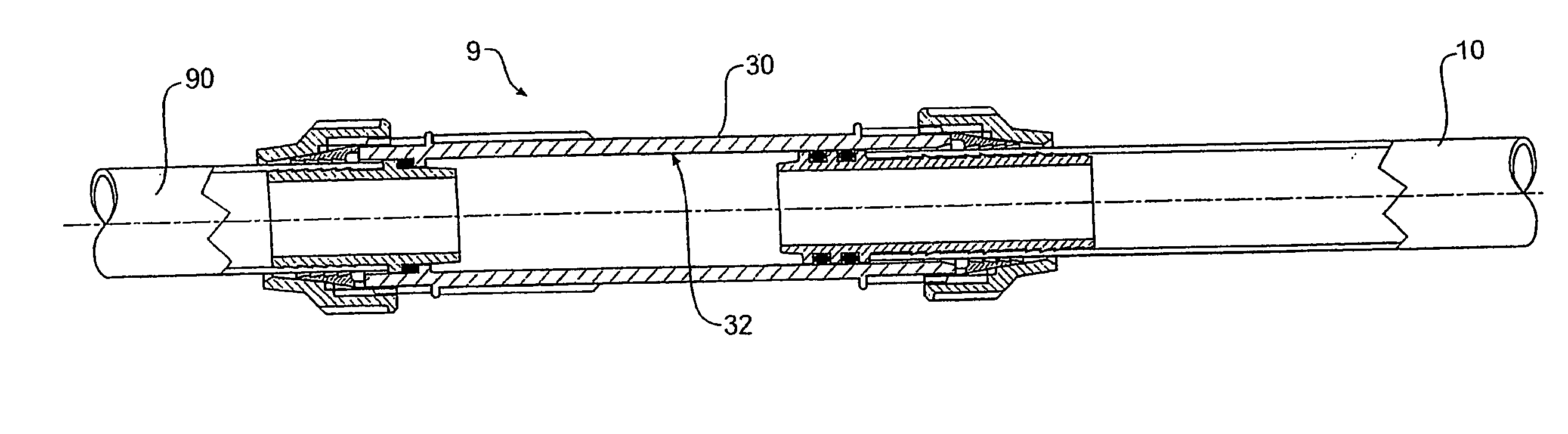
[0029]FIG. 6 is an enlarged view of the slip type pipe joint of FIG. 5.

[0030]FIG. 7 is a cross-sectional view showing the components of the slip type pipe joint of FIG. 6.

[0031]FIGS. 8, 9 and 10 show the slip type pipe joint of FIG. 6 at progressive stages of assembly; while

[0032]FIGS. 11 and 12 show an alternative embodiment of the invention.

[0033]Referring to FIGS. 1 and 2a, two spaced apart polymeric pipe...


PUM


Abstract

A slip type pipe fitting for joining two spaced apart plastic pipe ends is disclosed. The fitting includes: a first insert 12 having an elongate pipe support portion 14, insertable into an internal bore of a first plastic pipe end 11, and a distal end 16 in use projecting outside the first pipe end 11 and having a first annular seal 17; an elongate hollow pipe connector 30 defining a bore 32 and having first and second connector ends 40, 50, the inner bore 32 receiving the distal end 16 and first annular seal 17 of the first insert 12 for sliding movement and sealing therein; and a first compression joining assembly including a first end nut 42 for mechanically joining the first connector end 40 to the first pipe end 11 by a compression action sandwiching the first pipe end 11 between the first end annular member 42 and the pipe support portion 14 thereby locking the connector 30 with respect to the first pipe end 11. In use the support portion 14 extends into the first pipe end 11 an axial distance AL such that said locking can occur over a range of axial positions.

Description

FIELD OF THE INVENTION[0001]The present invention relates to pipe joining, repair and pipe take-off methods and pipe fittings therefor. The invention relates in particular to methods and pipe fittings suitable for sealably joining spaced-apart axially aligned pipe ends in above and below ground applications.BACKGROUND[0002]Low cost irrigation pipes or “rural pipes” are commonly made with nominal diameters of ½, ¾, 1, 1¼, 1½ and 2 inches in polyethylene plastic. Such pipes are typically thin walled and joined by mechanical compression fittings. Generally, thin walled pipes are imperial sized and require a barbed insert or liner to act as a stiffener to prevent the pipe wall from collapsing under compression and to provide a tail or spigot having a specific sized outer diameter for insertion into the fitting. In some cases both imperial and metric sized pipes require a barbed insert or liner depending on their pressure rating.[0003]Compression fittings or mechanical couplings for Aust...

Claims


Application Information

Patent Timeline
IPC IPC(8): F16L25/00
CPCF16L27/12F16L25/12F16L27/1273F16L13/143F16L13/146F16L33/2071
Inventor PHILLIPPS, GUY MALCOLM
Owner JTL AUSTRALIA
Why Eureka
Try Eureka