
Hydraulic tandem elastic drive mechanism and experiment platform for testing same

A series elastic and driving mechanism technology, applied in the field of hydraulic servo control, can solve problems such as heavy weight, time and manpower consumption, and complicated debugging, and achieve the effect of small space, light weight, and meeting the experimental requirements

Active Publication Date: 2017-08-15
HUAZHONG UNIV OF SCI & TECH
View PDF1 Cites 4 Cited by
  • Summary
  • Abstract
  • Description
  • Claims
  • Application Information

AI Technical Summary

Problems solved by technology

However, the currently used series elastic drive unit generally has a complex structure and a large weight, which is not very convenient to use, and generally can only realize force transmission in a single direction
Moreover, relevant experiments are still needed to verify whether the drive unit can meet the design requirements, but the debugging of the experimental platform currently used is also relatively complicated, so that it takes a lot of time and manpower to conduct experiments on the series elastic drive unit

Method used


Image

  • Hydraulic tandem elastic drive mechanism and experiment platform for testing same
  • Hydraulic tandem elastic drive mechanism and experiment platform for testing same
  • Hydraulic tandem elastic drive mechanism and experiment platform for testing same

Examples


Embodiment Construction

[0023] In order to make the object, technical solution and advantages of the present invention clearer, the present invention will be further described in detail below in conjunction with the accompanying drawings and embodiments. It should be understood that the specific embodiments described here are only used to explain the present invention, not to limit the present invention. In addition, the technical features involved in the various embodiments of the present invention described below can be combined with each other as long as they do not constitute a conflict with each other.

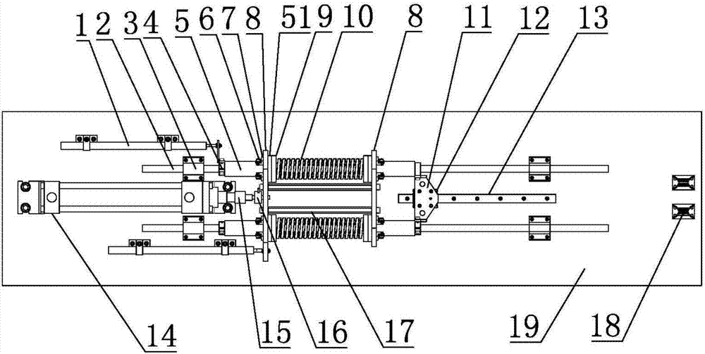
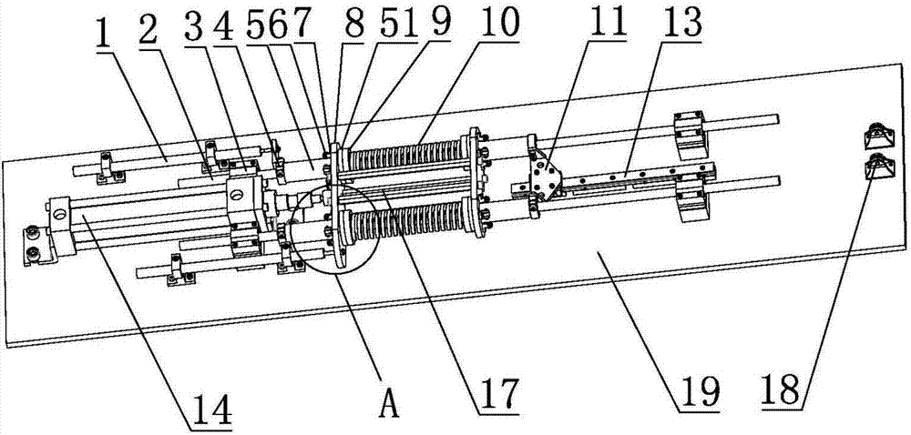
[0024] refer to Figure 1 ~ Figure 4 , a hydraulic series elastic driving mechanism, comprising a base plate 19 and a hydraulic cylinder 14 and an elastic unit that are jointly arranged on the base plate 19, wherein,

[0025] The output shaft of the hydraulic cylinder 14 is arranged horizontally and the output shaft of the hydraulic cylinder 14 is connected with a positioning frame, and the pos...


PUM


Abstract

The invention belongs to the field of hydraulic servo control, and discloses a hydraulic tandem elastic drive mechanism. The hydraulic tandem elastic drive mechanism comprises a bottom plate, a hydraulic cylinder and an elastic unit, wherein a location frame is connected to the output shaft of the hydraulic cylinder; the elastic unit comprises a bearing unit, a guide shaft, compression spring seats and compression springs; the bearing unit comprises a bearing seat arranged on the bottom plate and a first linear bearing arranged in the bearing seat; two shaft rings are arranged on the guide shaft; two second linear bearings are installed on the guide shaft in a penetrating manner; the shaft shoulders of the two second linear bearings are located between two location plates; the corresponding compression spring seat is installed on the shaft shoulder of each second linear bearing; and the corresponding compression spring is installed on each compression spring seat and installed on the guide shaft in a penetrating manner. The hydraulic tandem elastic drive mechanism disclosed by the invention is capable of simulating the stretching and compressing action of a joint, is capable of transferring a drive force in a stretching direction and a compressing direction, occupies less space, and is light in weight.

Description

technical field [0001] The invention belongs to the field of hydraulic servo control, and more specifically relates to a hydraulic series elastic drive mechanism and an experimental platform for testing it. Background technique [0002] Joint bionic drive technology has become an important research direction in the field of robotics. In terms of joint force servo drives, since the reducer increases the output impedance of the motor while increasing the force and energy density of the motor drive, it also increases the dynamics of the motor. The complexity and nonlinearity of the modeling makes precise force control of motor drives difficult. Similarly, in terms of hydraulic actuators, precise force control of hydraulic actuators is difficult due to the effects of cylinder friction, leakage, non-linear flow of oil, and high output impedance of the actuator itself. Therefore, motor-driven systems or hydraulic-driven systems are more suitable for speed or position control rath...

Claims


Application Information

Patent Timeline
IPC IPC(8): B25J9/14B25J19/00
CPCB25J9/144B25J19/0095
Inventor 高亮李硕李新宇董昊臻胡成颢王美思唐华彬钟浩然李星辰肖新安卢盛雨宋志涛
Owner HUAZHONG UNIV OF SCI & TECH
Learn More