Linear induction machine control scheme, systems, and methods

a linear induction machine and control scheme technology, applied in the field of induction, can solve the problems of ineffectiveness, high cost, and insufficient functionality of vector control, and achieve the effects of improving efficiency, reducing cost, and increasing complexity

Inactive Publication Date: 2008-11-06
BOARD OF RGT THE UNIV OF TEXAS SYST
View PDF5 Cites 13 Cited by
  • Summary
  • Abstract
  • Description
  • Claims
  • Application Information

AI Technical Summary

Problems solved by technology

Vector control does not provide sufficient functionality for LIM as for other types of machines, e.g., rotary induction machines (“RIM”) due to trailing eddy current effects and magnetic asymmetry effects.
Furthermore, vector control schemes are relatively complicated, expensive, and ineffective.

Method used


Image

  • Linear induction machine control scheme, systems, and methods
  • Linear induction machine control scheme, systems, and methods
  • Linear induction machine control scheme, systems, and methods

Examples


Embodiment Construction

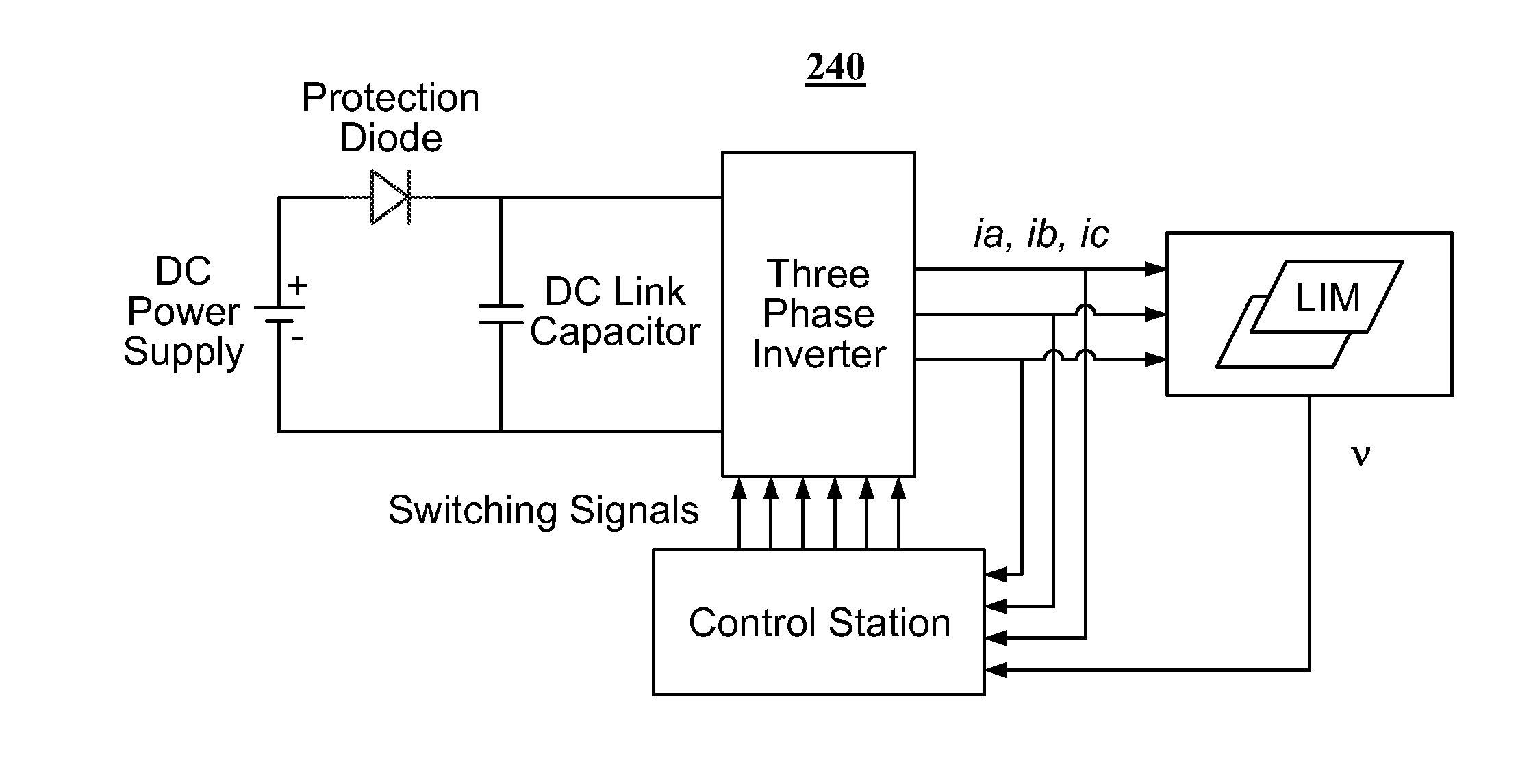
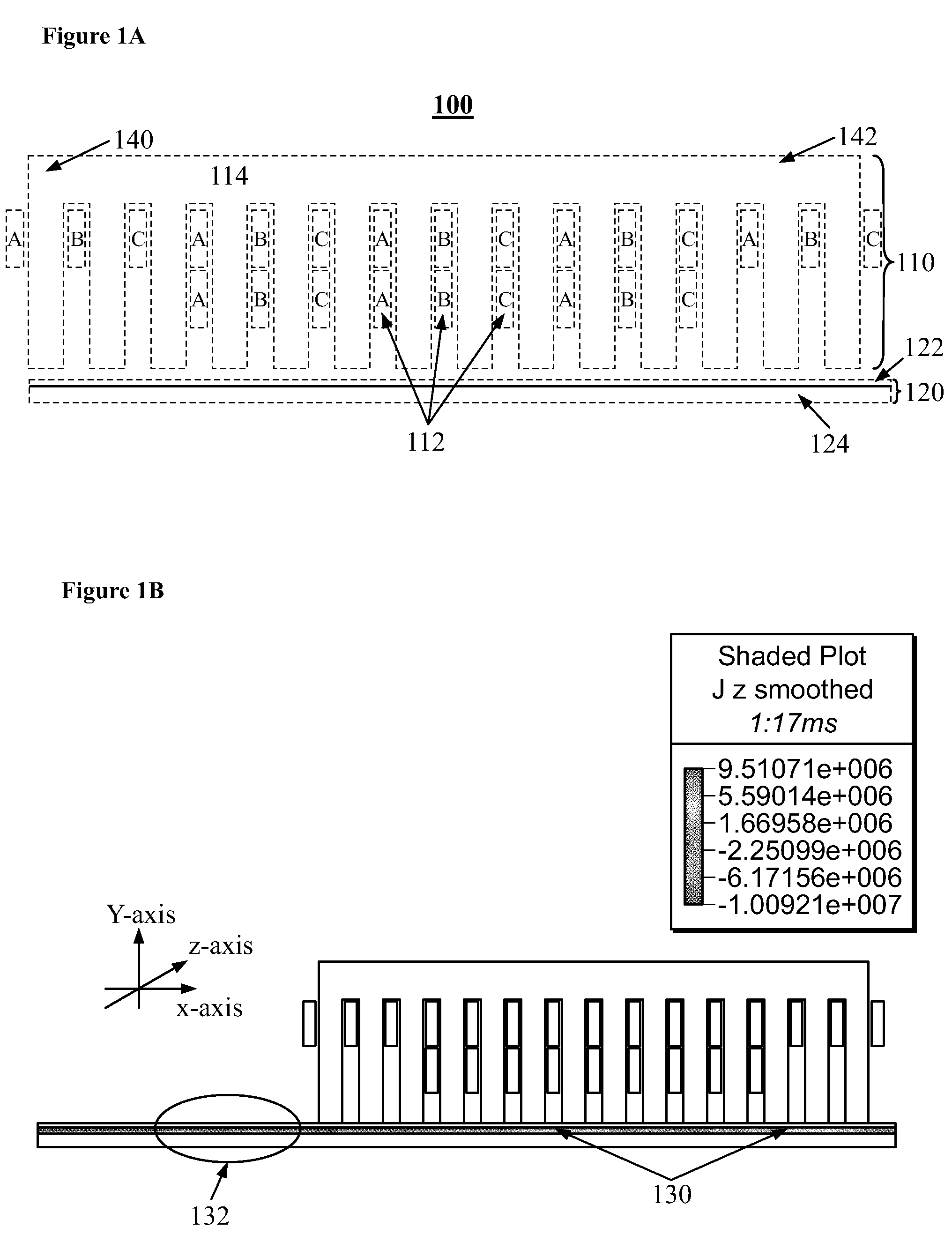
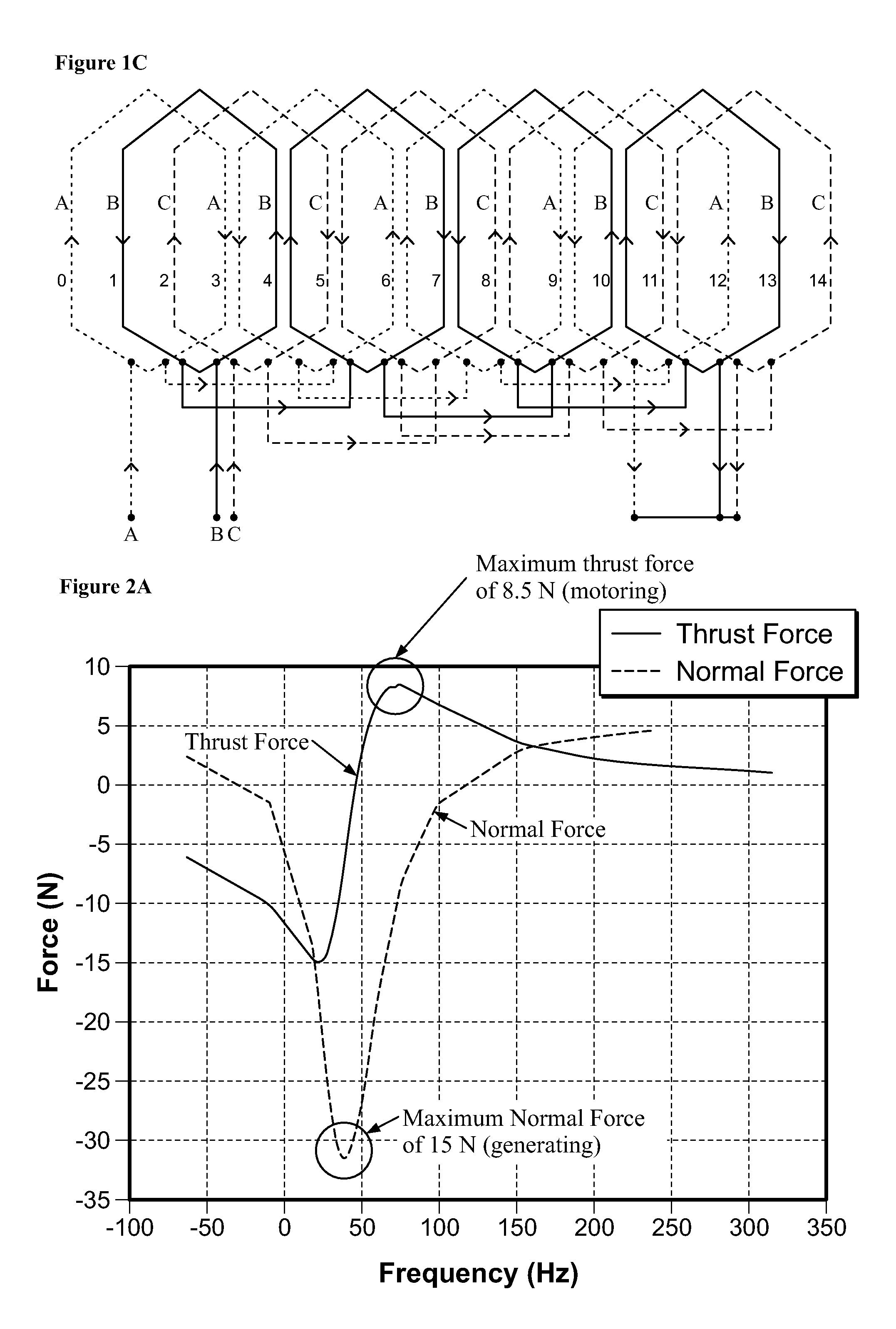
[0051]The methods, apparatuses, and systems can be understood more readily by reference to the following detailed description of the methods, apparatuses, and systems, and the following description of the Figures.

[0052]It is to be understood that the LIM system and control scheme may be applied to control motoring, generating, and electromagnetic braking regions in any linear induction machine. Generally speaking the linear induction machines that may avail benefits from the embodiments described herein include, but are not limited to, linear flat induction machines (single-sided and double-sided), tubular linear induction machines, and the like. Although particular embodiments are described with reference to one or more type variations of motors and / or generators, it should be expressly understood that such embodiments may be utilized with other variations of motors or generators. The LIM system and control scheme may be applied to any desired application, with appropriate modifica...


PUM


Abstract

A method and system for a control scheme for linear induction machines. The control scheme includes a maximum energy conversion ratio and a maximum acceleration and deceleration for linear induction machines.

Description

CROSS-REFERENCE TO RELATED APPLICATIONS[0001]This application claims priority to U.S. Provisional Application No. 60 / 927,230, filed on May 2, 2007, which is incorporated by reference herein.BACKGROUND OF THE INVENTION[0002]The embodiments described herein relates generally to the field of induction, and more particularly to induction drives, machines, and controls thereof.[0003]Vector control has been intensively utilized in linear induction machines (“LIM”) to achieve maximum speed acceleration and deceleration for linear induction machines. Vector control includes direct field oriented control and indirect field oriented control. Vector control does not provide sufficient functionality for LIM as for other types of machines, e.g., rotary induction machines (“RIM”) due to trailing eddy current effects and magnetic asymmetry effects. Furthermore, vector control schemes are relatively complicated, expensive, and ineffective.[0004]The embodiments described herein solve these problems,...

Claims


Application Information

Patent Timeline
Patent Type & Authority Applications(United States)
IPC IPC(8): H02K41/02H02P11/00
CPCH02P23/08H02P25/06H02P25/062H02P25/066
Inventor YU, HAIDONGFAHIMI, BABAK
Owner BOARD OF RGT THE UNIV OF TEXAS SYST
Why Eureka
Try Eureka