
Lens module

Inactive Publication Date: 2008-11-06
INT CURRENCY TECH
View PDF2 Cites 18 Cited by
  • Summary
  • Abstract
  • Description
  • Claims
  • Application Information

AI Technical Summary

Benefits of technology

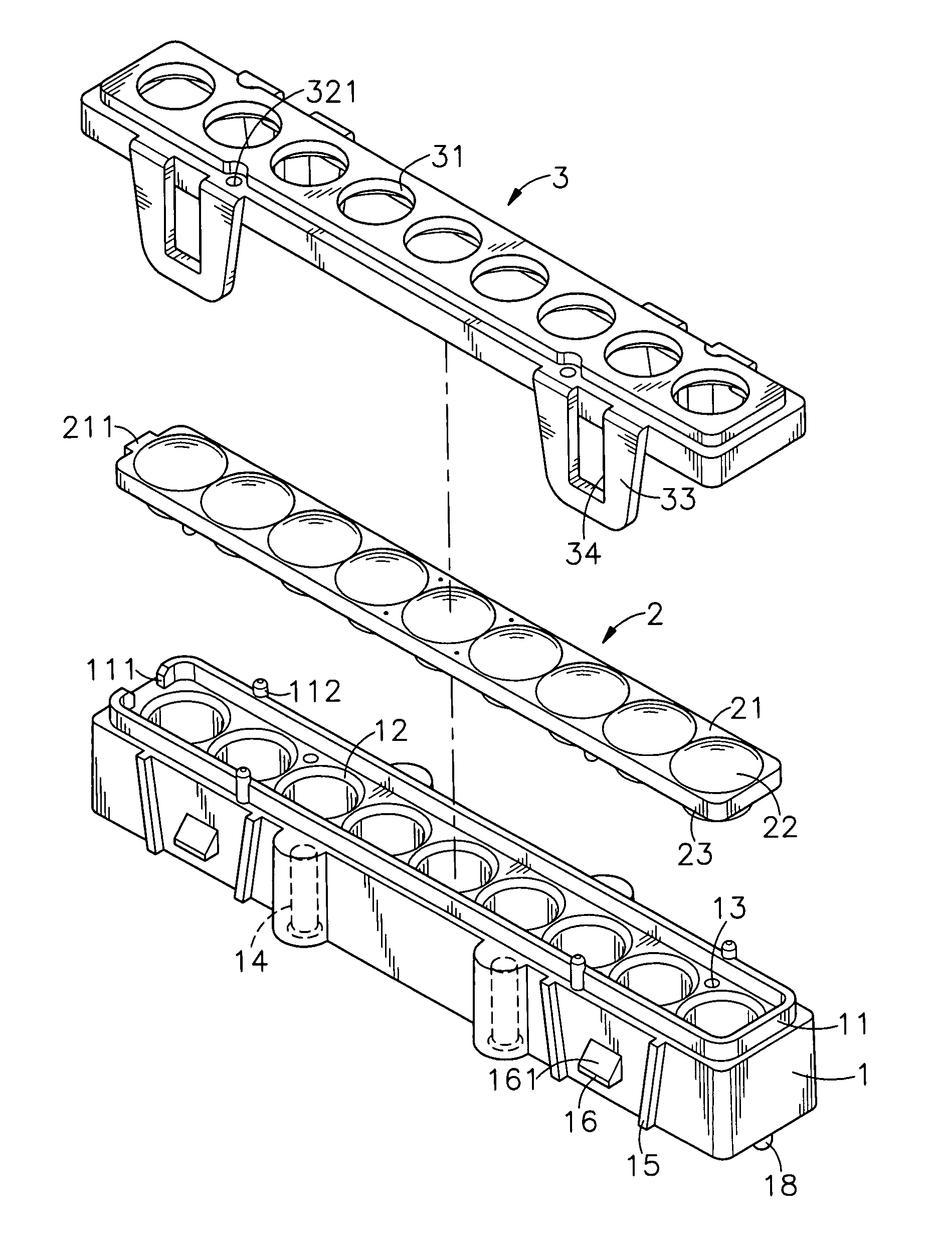
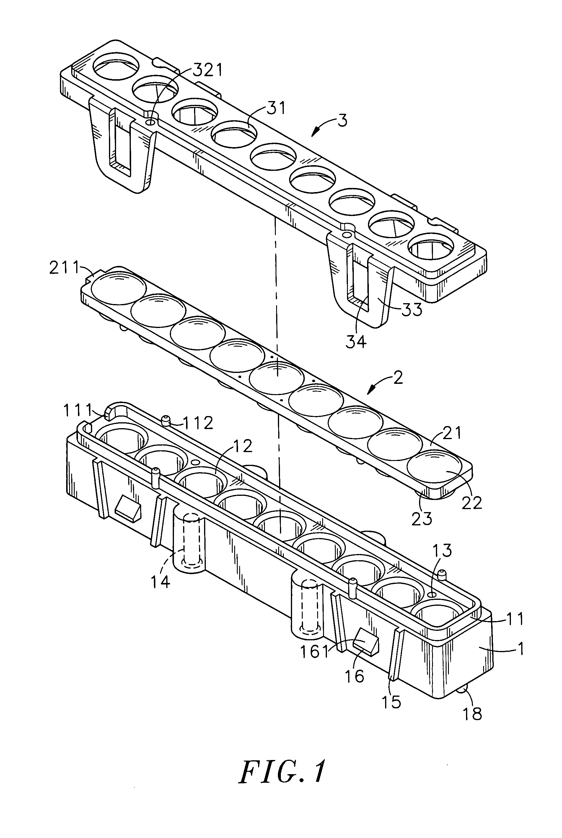
[0015]According to one aspect of the present invention, the lens module is comprised of a holder base, a lens device mounted in the top side of the holder base, and a top cover capped on the holder base to hold down the lens device. The holder base has a top flange protruded from the top side, a foolproof notch at one end of the top flange, and a plurality of locating holes bilaterally asymmetrically disposed in the top side within the area defined by the top flange. The lens device is press-fitted into the space surrounded by the top flange, having a protruding block engaged into the foolproof notch and a plurality of locating pins respectively fitted into the locating holes of the holder base. Thus, the lens device is accurately and positively positioned in between the holder base and the top cover.
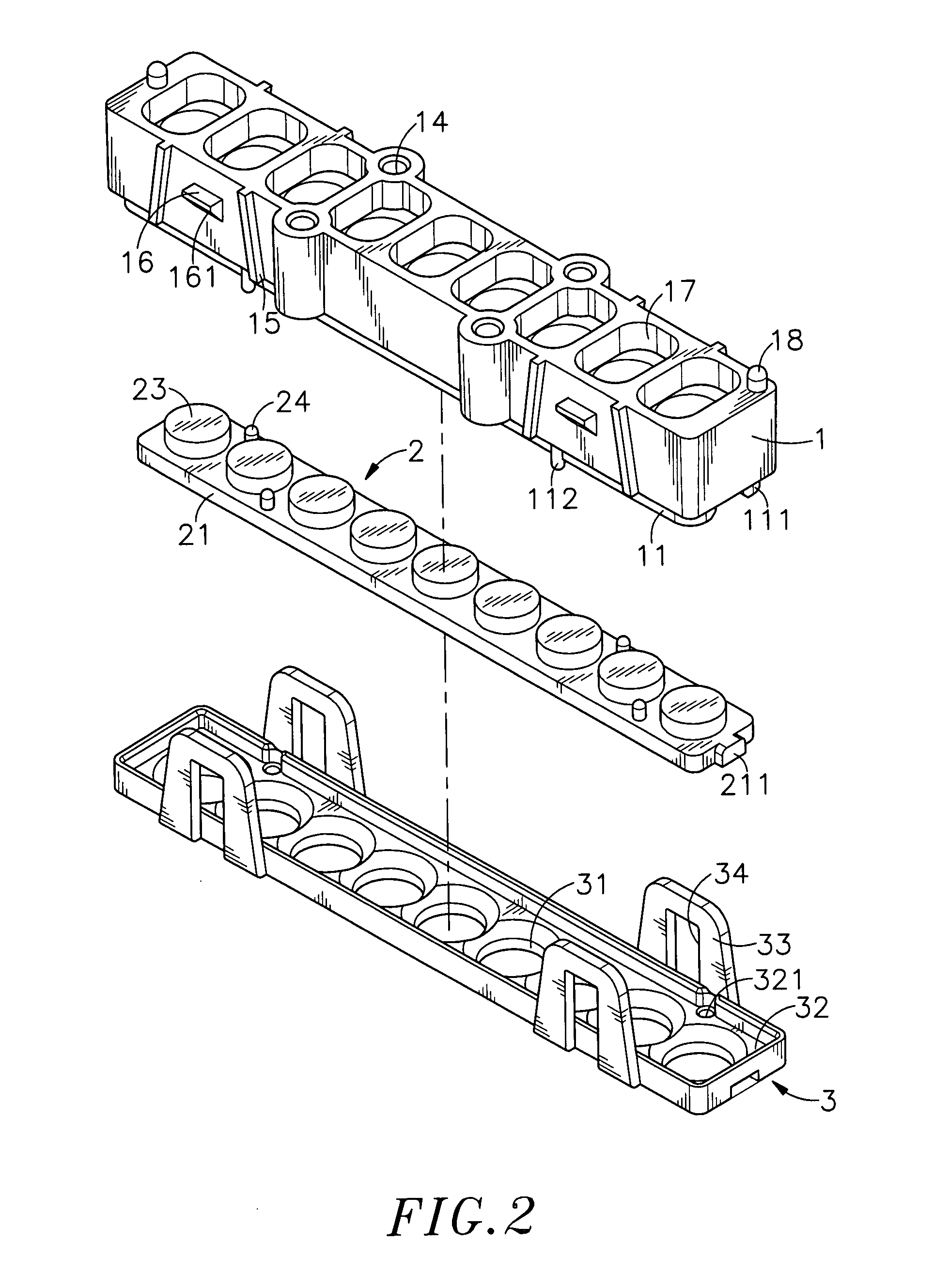
[0017]According to still another aspect of the present invention, the lens module is designed for use in a bill acceptor. During application, the flat protrusions and the convex portions of the lens device of the lens module at the circuit board of the light-emitting unit of the bill acceptor direct different wavelengths of light from the LEDs of the associating circuit board to the convex portions of the lens device of the lens module at the circuit board of the light-receiving unit of the bill acceptor so that the flat protrusions of the lens device of the lens module at the circuit board of the light-receiving unit condense respective light beams onto the sensors of the associating circuit board for bill authenticity verification. This design prevents interference among light beams from different LEDs, improving the verification accuracy of the bill acceptor.

Problems solved by technology

However, venders and consumers are always assailed by the problem of counterfeit money since the use of paper currency.
Following development of computer technology, evil persons may use a computer to scan, copy and print paper money.
However, examining invisible anti-counterfeiting techniques requires a special machine or instrument to verity the authenticity.
However, the magnetic head tends to be contaminated by ink dirt, resulting in an inaccurate detection.
Further, a counterfeit currency maker may make a counterfeit currency that carrying similar magnetic inks to cheat the machine.
This computing procedure requires a certain length of time, not suitable for use in a vending machine to verify the authenticity of a paper money.5. The complicated structure of this design of valuable paper validator uses so many parts, resulting in a high manufacturing cost.
Ultraviolet lamps are not suitable for use in a bill validator for vending machine.
When an ultraviolet lamp type bill validator is used in an outdoor vending machine, air moisture may pass through gap between the lamp bulb and the electric socket, causing a short circuit.
Further, an ultraviolet lamp consumes much electric power and releases much heat energy during operation.
Further, an ultraviolet lamp has a big side and a short working life, and is easy to break.

Method used


Image

  • Lens module
  • Lens module
  • Lens module

Examples


Embodiment Construction

[0028]Referring to FIGS. 1˜4, a lens module in accordance with the present invention is shown comprised of a holder base 1, a lens device 2 and a top cover 3.

[0029]The holder base 1 is a narrow elongated member having a top flange 11 upwardly extending from its top side, a plurality of vertical through holes 12 arranged in a row and surrounded by the top flange 11, a plurality of locating holes 13 formed on its top side and asymmetrically arranged at two opposite sides relative to the row of through holes 12 within the area surrounded by the top flange 11, a foolproof notch 111 at one end of the top flange 11, a plurality of locating rods 112 asymmetrically provided at two sides of the top flange 11 and protruding over the topmost edge of the top flange 11, a plurality mounting portions 14 symmetrically disposed at its two opposite lateral sides for fastening to a circuit board, a plurality of guide tracks 15 symmetrically arranged at its two opposite lateral sides and gradually red...


PUM


Abstract

A lens module includes a holder base, which is affixed to a circuit board and has bottom receiving holes for receiving LEDs or sensors on the circuit board and a top flange with a foolproof notch, a lens device press-fitted into the top flange and secured to the foolproof notch to ensure accurate positioning and having flat protrusions engaged into respective through holes in the holder base in alignment with the LEDs or sensors, and a top cover capped on the holder base to hold down the lens device and having through holes that receive convex portions of the lens device respectively.

Description

BACKGROUND OF THE INVENTION[0001]1. Field of the Invention[0002]The present invention relates to lens modules and more particularly, to a lens module for use in a bill acceptor for detecting the authenticity of a bill, and the lens module has multiple positioning structures to have a lens device positively and accurately positioned in between a holder base and a top cover.[0003]2. Description of the Related Art[0004]Following fast development of technology, our mode of living has been changed. Various automatic vending machines (card dispensers, ticket vending machines, money exchanging machines, etc.) are used everywhere to sell any of a variety of products without serviceman. Providing automatic vending machines saves much labor cost, and brings great convenience to consumers. A money-exchanging machine generally comprises a coin acceptor and a bill acceptor.[0005]However, venders and consumers are always assailed by the problem of counterfeit money since the use of paper currency...

Claims


Application Information

Patent Timeline
IPC IPC(8): G02B7/02G06K9/74
CPCG02B7/023G07D7/121
Inventor YANG, WEN-FUTSAI, HAI-ENYANG, YA-HUEICHEN, WEI-JR
Owner INT CURRENCY TECH
Learn More