Multi-Modal Imaging Registration Calibration Device and Method

a multi-modal imaging and calibration device technology, applied in tomography, instruments, applications, etc., can solve problems such as misalignment between the bed, pet, and ct positions, and the scan not working so well for multiple-position scans

Inactive Publication Date: 2008-11-06
SIEMENS MEDICAL SOLUTIONS USA INC
View PDF2 Cites 11 Cited by
  • Summary
  • Abstract
  • Description
  • Claims
  • Application Information

AI Technical Summary

Problems solved by technology

While such an arrangement has worked well for calibrating a single-position scan, it has not worked so well for multiple-position scans, and errors of as much as 2.5 millimeters in image registration have been measured.
It is believed that such errors arise because the precise motion of the patient bed is not perfectly known or predictabl

Method used


Image

  • Multi-Modal Imaging Registration Calibration Device and Method
  • Multi-Modal Imaging Registration Calibration Device and Method
  • Multi-Modal Imaging Registration Calibration Device and Method

Examples


Embodiment Construction

[0014]Phantom

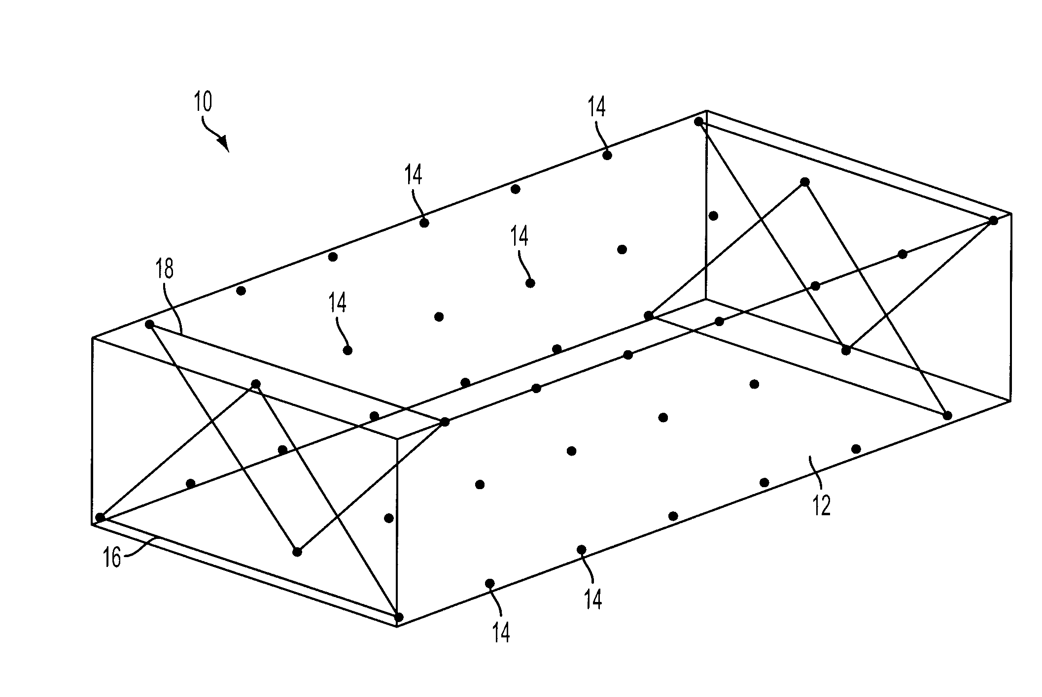
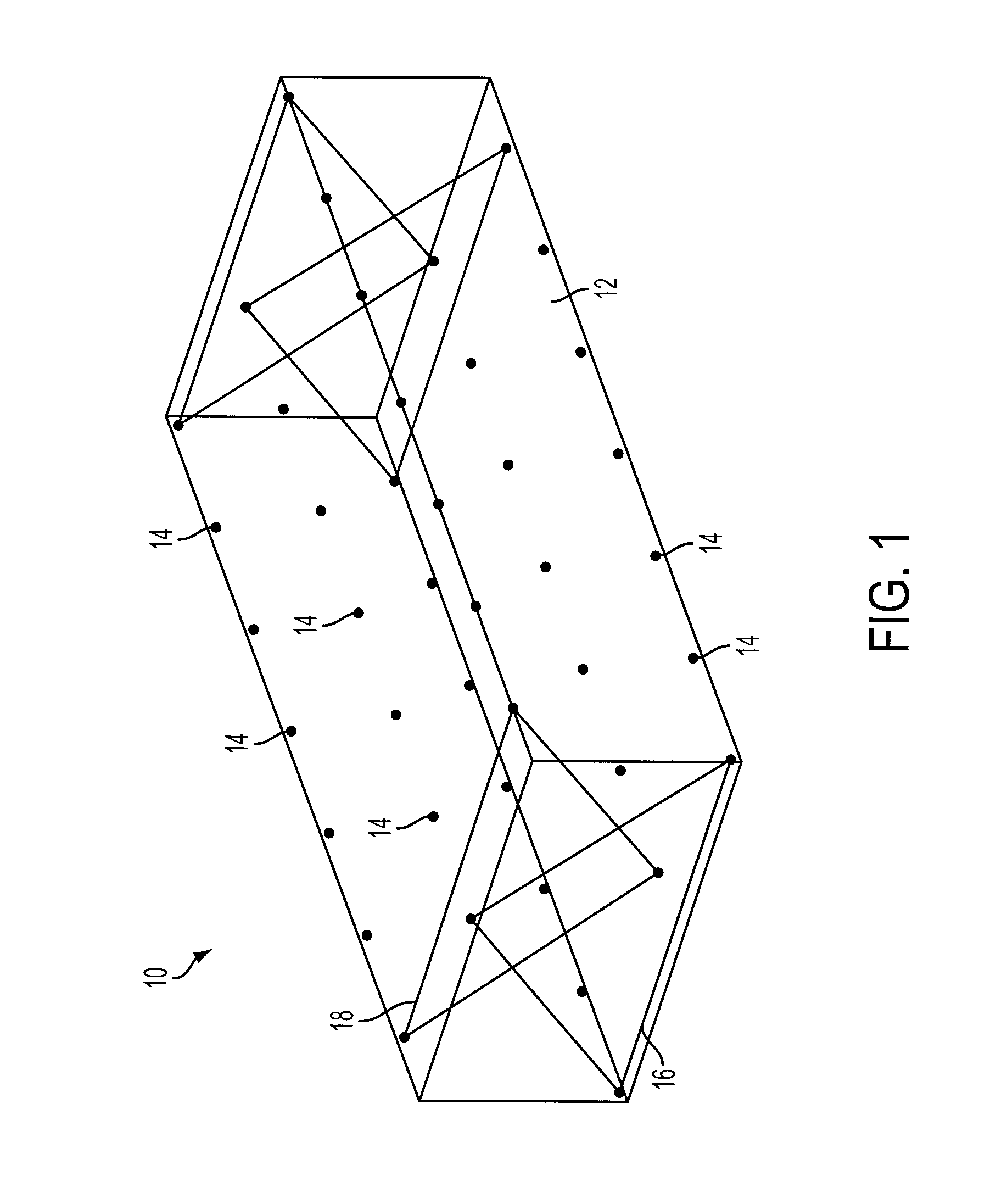
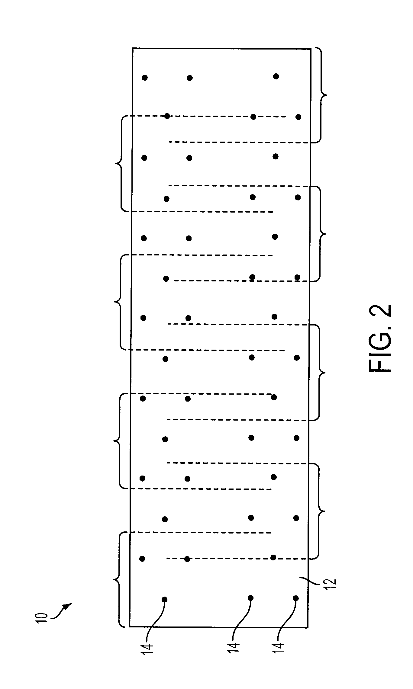
[0015]A scan calibration device (phantom) 10 according to the invention is illustrated in FIGS. 1 through 4. The phantom 11 includes a support member 12 and a multiplicity of emission point sources 14 embedded in and distributed across the support member in a highly precise arrangement, which is described below.

[0016]The support member 12 is a generally rectilinear, brick-shaped member that is long enough to provide calibration for an entire body scan. For current scanning systems, 90 centimeters is sufficient length. Although a perfectly square cross-section (taken transverse to the lengthwise axis of the support member) might be ideal, the phantom 10 must fit on top of the pallet of the patient handling system. Therefore, a rectangular cross-section allows for maximum spreading of the point sources on top of the pallet while still allowing the phantom 10 to fit within the tunnel of the scanning system gantry. For current scanning systems, a width of 16 inches (40.64 c...


PUM


Abstract

A phantom and associated method for calibrating registration in a multi-modal medical diagnostic imaging system are presented. The phantom features a plurality of emission point sources arranged in multiple parallel planes along the length of the phantom, with enough planes to allow mode registration to be calibrated over the length of an entire full-body scan. According to the method, calibration scans are performed at each of several scan positions along the length of the phantom, with at least two planes of emission point sources covered by the scan at each position.

Description

FIELD OF THE INVENTION[0001]In general, the invention relates to multi-modal medical diagnostic imaging. More particularly, the invention relates to a device and method used to calibrate registration between the different imaging modes of a multi-modal imaging system.BACKGROUND OF THE INVENTION[0002]Diagnostic imaging systems which use multiple imaging modalities are known in the art. For example, it is known to combine CT and PET sub-systems in a multi-modal imaging system to obtain synergistic advantages above and beyond the imaging advantages provided by each type of imagining modality individually. With such a multi-modal system, one imaging modality provides one type of information—for example, the CT modality can provide structural or anatomical patient data while the other imaging modality provides another type of information—for example, the PET modality provides functional (e.g., blood flow) patient data. Additionally, data from an initial or preliminary CT scan of a patien...

Claims


Application Information

Patent Timeline
IPC IPC(8): G01D18/00
CPCA61B6/037A61B6/583
Inventor RAPPOPORT, VITALIYHAYDEN, CHARLESSTOUGHTON, ROBERT SMITH
Owner SIEMENS MEDICAL SOLUTIONS USA INC
Why Eureka
Try Eureka